Chrysler RG Voyager. Manual - part 736
(4) Using an appropriate scan tool, check any
erase any power liftgate control module diagnostic
trouble codes related to the door motor assembly.
(5) Verify power liftgate system operation. Cycle
the power liftgate through one complete open and
close cycle, this will allow the power liftgate control
module to relearn its cycle with the new components.
CAUTION: Torque link rod to liftgate attachment
bolt to 250 in. lbs. Care must be taken not to over-
torque link rod bolt.
PINCH SENSOR
DESCRIPTION
Pinch sensors are located on each side of the lift-
gate (Fig. 19). These sensors look like weather-strips,
however they consist of pieces of electrically conduc-
tive rubber (tapeswitch), wires, resistor, double sided
tape, and a plastic carrier. They are used to indicate
an obstruction during a power liftgate close cycle.
OPERATION
During a power liftgate close cycle, if either of the
two conductive rubber strips (tapeswitch) of the
pinch sensor come in contact with an obstacle, the
pinch sensor circuit is completed. This tells the
power liftgate control module that a obstruction is
felt. The control module will stop the liftgate imme-
diately and return it to the full open position.
REMOVAL
(1) Disconnect and isolate the battery negative
cable.
(2) Remove trim panel from liftgate, (Refer to 23 -
BODY/DECKLID/HATCH/LIFTGATE/TAILGATE/
TRIM PANEL - REMOVAL).
(3) Disconnect the pinch sensor wire harness con-
nector (Fig. 20).
(4) Remove screws holding the pinch sensor to lift-
gate.
(5) Feed the pinch sensor wire harness out of the
liftgate and remove the sensor from the vehicle.
INSTALLATION
WARNING: USE EXTREME CAUTION WHEN TEST-
ING PINCH SENSOR OPERATION.
CAUTION: Ensure liftgate surface is clean and dry
prior to pinch sensor installation. Failure to do so
will inhibit the adhesive backings ability to adhere
to the liftgate and cause improper system operation
or premature component failure.
(1) Position the pinch sensor to the liftgate.
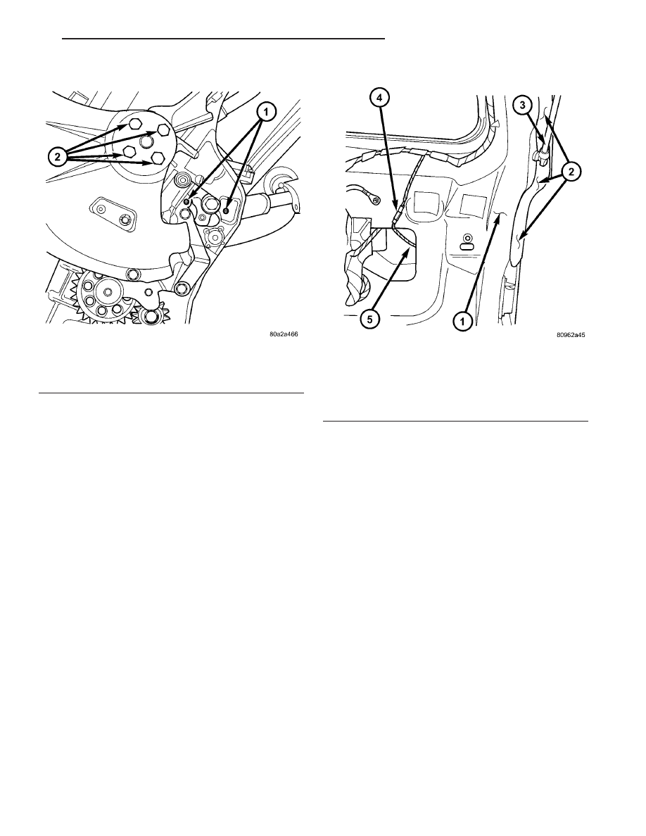
Fig. 18 LIFTGATE GEAR MOTOR ASSEMBLY
1 - ENGAGE ACTUATOR RETAINING SCREWS
2 - LIFT GEAR RETAINING BOLTS
Fig. 19 PINCH SENSOR LOCATION
1 - LIFTGATE
2 - PINCH SENSOR ASSEMBLY
3 - LIFTGATE PROP ROD
4 - PINCH SENSOR WIRE HARNESS CONNECTOR
5 - PINCH SENSOR WIRE HARNESS
RS
POWER LIFTGATE SYSTEM
8N - 17
LIFT GEAR & LINK ROD (Continued)