Chrysler RG Voyager. Manual - part 696
OPERATION
The module has a number of functions:
• Supply voltage to the sensors and display.
• Disconnection of the display with bus idle and
over voltage Vmax.
• Triggering the sensors.
• Analyze echo delay times and calculate obstacle
distances.
• Bi-directional data communication to the display
for diagnosis.
• System diagnostics - diagnosis and error han-
dling (sensors, display, module).
• Data exchange over the Programmable Commu-
nication Interface (PCI) data bus.
The system detection length from the rear of the
vehicle is 0.3 meters to 1.5 meters. This area extends
around the rear side of the vehicle. The system detec-
tion height from the ground is 0.2 meters to about
1.5 meters. The radio mutes when the system acti-
vates its audible tone.
When the driver selects Reverse, the system scans
for objects behind the vehicle using four sensors
located in the rear bumper. Objects can be detected
from up to 1.5 meters. A warning display above the
rear window provides both visible and audible warn-
ings indicating the range of the object.
The system is active only when the vehicle is in
reverse for vehicle speeds less than 16 Km/h (10
mph). If the vehicles Parking/Emergency Brake is
applied, the system is deactivated.
The display contains two sets of yellow and red
Light Emitting Diode’s (LED’s) that the driver can
see as they look over their shoulder while backing
up. Each side of the vehicle has its own warning
LED’s. The system provides a visual warning by illu-
minating one or more yellow LED’s as the vehicle
gets closer to the object. As the vehicle continues to
approaches the object, one red LED is illuminated
and the system emits a series of short beeps. The
tone will remain constant and both red LED’s are
illuminated once the vehicle is within 12 inches (30.5
cm) of the object.
The system can be turned ON or OFF through the
Electronic Vehicle Information Center (EVIC) when
the vehicle is in PARK. If the park assist system is
turned OFF, a single chime will sound and the EVIC
will display the following message “REAR PARK
ASSIST OFF”, when the vehicle is in reverse.
• Ensure that the rear bumper is free of dirt and
debris to keep the system operating properly.
• Jackhammers, large trucks, and other vibrations
could affect the performance of the system.
• Ensure that the parking brake is not applied.
If “Service Park Assist System” appears in the
EVIC after making sure the rear bumper is clean,
proceed to diagnose the system using a scan tool and
the appropriate diagnostic information.
To diagnose the Park Assist Module, use a scan
tool and the appropriate body diagnostic information.
REMOVAL
(1) Open hood.
(2) Disconnect and isolate the battery negative
cable.
(3) Remove the left quarter trim panel (Refer to 23
-
BODY/INTERIOR/QUARTER
TRIM
PANEL
-
REMOVAL).
(4) Disconnect the Park Assist Module electrical
connector (Fig. 6).
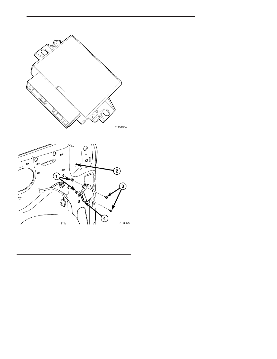
Fig. 4 PARK ASSIST MODULE
Fig. 5 PARK ASSIST MODULE - LOCATION
1 - RETAINING SCREW J-CLIPS
2 - LEFT QUARTER PANEL/C-PILLAR
3 - MODULE RETAINING SCREWS
4 - PARK ASSIST MODULE
RS
CHIME/BUZZER
8B - 5
PARK ASSIST MODULE (Continued)