Chrysler RG Voyager. Manual - part 636


  Index      Chrysler     Chrysler RG Voyager - service repair manual 2005 year


Search            


Content   ..  634  635  636  637   ..


Chrysler RG Voyager. Manual - part 636


The Front-Wheel-Drive with Fold-in-Floor Seating

rear suspension is very much like the FWD rear sus-

pension except for the fact that the stabilizer bar
mounts in from of the axle.

The All-Wheel-Drive (AWD) rear suspension uses a

unique axle that is mounted to multi-leaf springs,
and does not use isolator bushings between the rear
axle and the leaf springs.

The Front-Wheel-Drive Cargo rear suspension uses

multi-leaf springs and a different rear axle than
either the standard FWD or AWD. It also does not
utilize a stabilizer bar. It is very similarly to the
AWD suspension.

The rear suspension consists of these major compo-

nents:

• Leaf springs (One each side)

• Jounce bumpers (One each side)

• Shock absorbers (One each side)

• Hub and bearings (One each side)

• Track bar

• Stabilizer bar

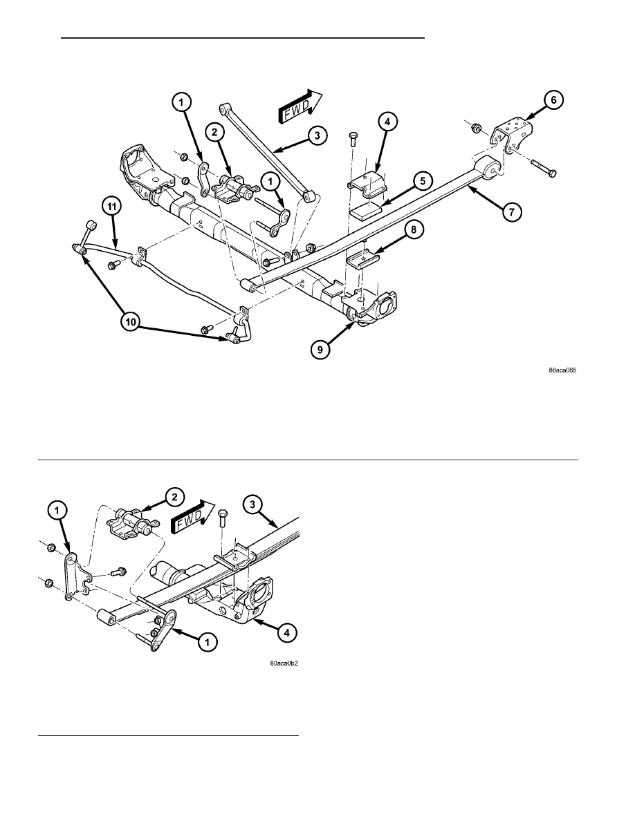
Fig. 1 Front-Wheel-Drive Rear Suspension

1 - SHACKLE

7 - LEAF SPRING (MONO-LEAF)

2 - REAR MOUNT (HANGER)

8 - ISOLATOR

3 - TRACK BAR

9 - FWD REAR AXLE

4 - SPRING PLATE

10 - STABILIZER BAR LINKS

5 - ISOLATOR

11 - STABILIZER BAR

6 - FRONT MOUNT (HANGER)

Fig. 2 All-Wheel-Drive Rear Suspension

1 - SHACKLE
2 - REAR MOUNT (HANGER)
3 - LEAF SPRING (MULTI-LEAF)
4 - AWD REAR AXLE

RS

REAR SUSPENSION

2 - 27

REAR SUSPENSION (Continued)

SPECIFICATIONS

REAR SUSPENSION FASTENER TORQUE

DESCRIPTION

N·m

Ft.

Lbs.

In.

Lbs.

Hub And Bearing Mounting
Bolts

129

95

Hub And Bearing Axle Hub
Nut

244

180

Jounce Bumper Mounting
Bolt

33

24

290

Leaf Spring Front Mount-To-
Body Bolts

61

45

Leaf Spring Front Pivot Bolt

156

115

Leaf Spring Plate-To-Axle
Bolts

95

70

Leaf Spring Rear Mount-To-
Body Bolts

61

45

Leaf Spring Shackle Plate
Nuts

61

45

Shock Absorber Mounting
Bolts

88

65

Stabilizer Bar Bushing
Retainer Bolts

61

45

Stabilizer Bar Link Nuts

61

45

Stabilizer Bar Link Frame
Bracket Mounting Bolts

61

45

Track Bar Bracket-To-Body
Mount Bolts

61

45

Track Bar Pivot Bolts

95

70

Wheel Mounting (Lug) Nut

135

100

SPECIAL TOOLS

REAR SUSPENSION

Remover, Hub/Bearing 8458

Remover/Installer, Bushing 8459

Remover/Installer, Bushing 8526

Press, Ball Joint C-4212F

2 - 28

REAR SUSPENSION

RS

REAR SUSPENSION (Continued)

BUSHING - LEAF SPRING
FRONT

REMOVAL

(1) Raise vehicle on frame-contact hoist as follows:

(a) Position the hoist arm supporting the corner

of the vehicle to be serviced against a block of wood
placed on the body sill as shown (Fig. 3).

(b) Position the remaining hoist arms at each

corner of the vehicle in the normal fashion. (Refer
to LUBRICATION & MAINTENANCE/HOISTING
- STANDARD PROCEDURE)

(c) Raise the vehicle to a comfortable working

level.

(2) Position an under-hoist utility jack or transmis-

sion jack under rear axle toward the side needing
bushing replacement. Jack pad should just contact
axle.

(3) Remove shock absorber lower mounting bolt.

NOTE: If shock absorber bolt deflects upward dur-
ing removal, raise axle by adjusting support jack. If
shock absorber bolt deflects downward during
removal, lower axle by adjusting support jack (or by
pulling on axle).

(4) Remove four bolts securing leaf spring front

mounting bracket to the body (Fig. 3).

(5) Using jack, slowly lower rear axle, permitting

the forward end of rear spring to hang down. Lower
it enough to allow access to spring pivot bolt. It may

be necessary to place a wooden block between the
spring and vehicle to hold forward end of the spring
in place.

(6) Remove leaf spring forward pivot bolt, then

remove mounting bracket.

(7) Straighten the retainer tabs on the bushing

(Fig. 4).

(8) Place Remover/Installer, Special Tool 8459 on

leaf spring and bushing as shown (Fig. 5) and tighten
Set Screw securing Remover Plate to tool threaded
shaft.

Fig. 3 Lifting Point And Spring Mount

1 - BODY SILL AREA
2 - MOUNTING BOLTS
3 - SPRING MOUNTING BRACKET
4 - LEAF SPRING
5 - HOIST LIFT ARM
6 - WOODEN BLOCK

Fig. 4 Straightened Retaining Tabs

1 - SPRING EYE
2 - RETAINING TABS

Fig. 5 Tool 8459 Mounted For Bushing Removal

1 - BUSHING
2 - BEARING
3 - WASHER
4 - NUT
5 - BODY (8459-1)
6 - PIN
7 - REMOVER PLATE (8459-2)
8 - SET SCREW

RS

REAR SUSPENSION

2 - 29

(9) Tighten nut (Fig. 5), removing bushing from

spring eye.

(10) Remove the tool from spring, then remove

bushing from tool.

INSTALLATION

(1) Install by hand NEW bushing in left side of

leaf spring eye.

(2) Place Remover/Installer, Special Tool 8459 on

leaf spring and bushing as shown (Fig. 6) and tighten
Set Screw securing Installer Plate (8459–3) to tool
threaded shaft.

(3) Tighten nut (Fig. 6), installing bushing in

spring eye. Tighten nut until there is approximately
a 1 mm gap between the bushing flange and the
spring eye. Do not bottom the flange against the
spring eye.

(4) Remove Remover/Installer from the bushing

and leaf spring.

(5) Bend the retainer tabs on bushing outward

against spring eye.

(6) Position spring mounting bracket over spring

eye and install pivot bolt through center of bushing
from the outboard side.

NOTE: The pivot bolt must be installed from the
outboard side to allow proper bracket to body
mounting.

(7) Install the nut on the pivot bolt and lightly

tighten. Do not fully tighten bolt at this time.

(8) Raise the under-hoist utility jack or transmis-

sion jack, guiding the forward mounting bracket into
place against the body. It may help to use a drift
punch placed through the hole centered between the
mounting bolt holes in the bracket and the pilot hole
in the body of the vehicle as a guide. When the four
mounting bolt holes line up with their threads in the
body, Install the mounting bolts (Fig. 3). Tighten the
four mounting bolts to 61 N·m (45 ft. lbs.) torque.

(9) Raise or lower the jack until shock absorber

lower eye aligns with threads in axle housing. Install
shock absorber lower mounting bolt. Do not fully
tighten bolt at this time.

(10) Lower the vehicle and remove hoist arms and

block of wood from under vehicle.

(11) Tighten the spring front pivot bolt to 156 N·m

(115 ft. lbs.) torque.

(12) Tighten the lower shock absorber mounting

bolt to 88 N·m (65 ft. lbs.) torque.

HUB / BEARING

DESCRIPTION

The rear wheel bearing and rear wheel hub of this

vehicle are a one-piece sealed unit, or hub and bear-
ing unit type assembly (Unit III). The hub and bear-
ing is mounted to the center of the rear axle using 4
mounting bolts. It has five wheel mounting studs on
the hub flange.

All-Wheel-Drive vehicles have a hub and bearing

unit with a splined hole in the center of the hub for
rear driveshaft stub axle acceptance.

Front-Wheel-Drive vehicles with antilock brakes

have an internally mounted wheel speed sensor and
tone wheel. This hub and bearing can be identified
by the rounded cap and molded in connector on the
rear of the assembly (Fig. 7). The sensor and tone
wheel cannot be serviced separately from the hub
and bearing.

OPERATION

The hub and bearing has internal bearings that

allow the hub to rotate with the tire and wheel
assembly (and driveshaft on All-Wheel-Drive vehi-
cles). The five wheel mounting studs mount the tire
and wheel assembly, and disc brake rotor or brake
drum to the vehicle.

On All-Wheel-Drive vehicles, the splined mating of

the driveshaft stub axle and hub allows the drive-
shaft to rotate with the hub and wheel.

Front-Wheel-Drive vehicles equipped with antilock

brakes have a wheel speed sensor and tone wheel
mounted to the rear of the hub and bearing. The tone

Fig. 6 Tool 8459 Mounted For Bushing Installation

1 - NUT
2 - WASHER
3 - BEARING
4 - LEAF SPRING EYE
5 - BUSHING
6 - INSTALLER PLATE (8459-3)
7 - PIN
8 - BODY (8459-1)

2 - 30

REAR SUSPENSION

RS

BUSHING - LEAF SPRING FRONT (Continued)


Content   ..  634  635  636  637   ..