Chrysler RG Voyager. Manual - part 458
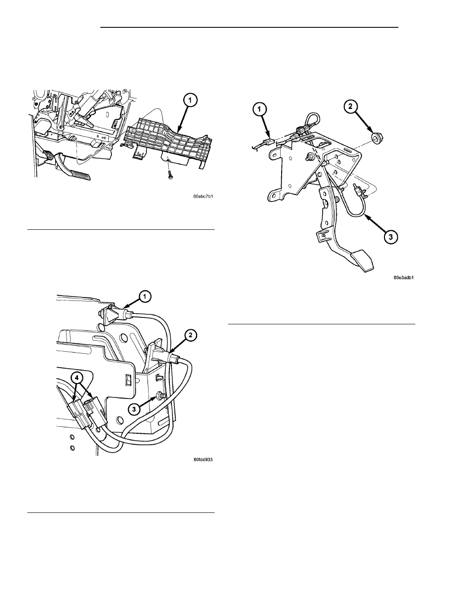
(3) Remove knee bolster (Fig. 30).
(4) Remove upstop switch by depressing four (4)
plastic wing tabs, and sliding switch through mount-
ing bracket. If necessary, remove mounting bracket
and remove switch (Fig. 31).
RHD
(1) Disconnect battery negative cable.
(2) Remove instrument panel lower silencer (Fig.
29).
(3) Remove knee bolster (Fig. 30).
(4) Disconnect upstop switch connector (Fig. 32).
(5) Remove upstop switch/bracket-to-clutch pedal
bracket nut. Remove switch (Fig. 32).
INSTALLATION
LHD
(1) Install upstop switch into bracket (Fig. 31).
Ensure switch wing tabs are fully expanded. If
removed, re-install bracket and torque to 13 N·m
(115 in. lbs.).
(2) Connect upstop switch connector.
(3) Install knee bolster (Fig. 30).
(4) Install instrument panel lower silencer (Fig.
29).
(5) Connect battery negative cable.
RHD
(1) Install switch and bracket assembly. Torque
nut to 12 N·m (110 in. lbs.) (Fig. 32).
(2) Connect upstop switch assembly (Fig. 32).
(3) Install knee bolster (Fig. 30).
(4) Install instrument panel lower silencer (Fig.
29).
(5) Connect battery negative cable.
Fig. 30 Knee Bolster—LHD Shown
1 - KNEE BOLSTER
Fig. 31 Interlock/Upstop Switch Location
1 - INTERLOCK SWITCH
2 - UPSTOP SWITCH
3 - RETAINER - UPSTOP BRACKET
4 - CONNECTORS
Fig. 32 Clutch Pedal Upstop Switch—RHD
1 - CONNECTOR
2 - NUT
3 - UPSTOP SWITCH/BRACKET
6a - 16
CLUTCH
RG
CLUTCH PEDAL UPSTOP SWITCH (Continued)