Chrysler RG Voyager. Manual - part 456
 

  Index      Chrysler     Chrysler RG Voyager - service repair manual 2005 year


Search            


Content   ..  454  455  456  457   ..


Chrysler RG Voyager. Manual - part 456


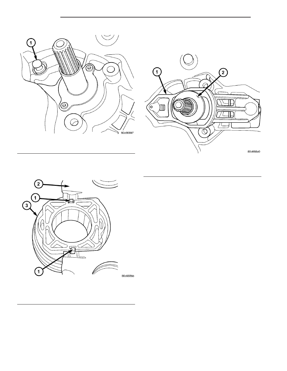
(2) Install clutch release bearing to lever. Apply

grease to interface points. Make sure release bearing
retainers engage lever pocket as shown in (Fig. 10).

(3) Apply grease to pivot ball, and on release lever

at slave cylinder contact point.

(4) Install clutch release bearing/lever assembly

into position by sliding bearing onto input bearing
retainer, and using moderate hand pressure to seat
release lever to pivot ball(s) (Fig. 11). A “pop” sound
should be heard. Verify proper engagement by lightly

pulling outward on lever at pivot ball location, and
then actuating lever and bearing to ensure proper
operation.

MASTER CYLINDER - RHD

REMOVAL

(1) Disconnect battery negative cable.
(2) Remove master cylinder to clutch pedal pin

retainer clip. Disengage pushrod from clutch pedal
pin (Fig. 13).

(3) Disengage master cylinder grommet from cowl

panel.

(4) Remove battery and tray.
(5) Diesel models: Remove windshield wiper mod-

ule assembly. (Refer to 8 - ELECTRICAL/WIPERS/
WASHERS/WIPER MODULE - REMOVAL)

(6) Discharge Air Conditioning system. (Refer to 24

- HEATING & AIR CONDITIONING/PLUMBING/
REFRIGERANT - STANDARD PROCEDURE)

(7) Remove suction/discharge line from evaporator

junction block.

(8) Using tool 6638A, disconnect clutch hydraulic

“quick-connect” fitting (Fig. 12).

(9) Remove clutch master cylinder tubing from

retainers in engine compartment.

(10) Remove clutch master cylinder from dash

panel/clutch pedal bracket by rotating 45° clockwise
and pulling outward towards engine (Fig. 13).

(11) Carefully guide clutch master cylinder and

hydraulic plumbing from engine compartment.

Fig. 9 Pivot Ball Position

1 - PIVOT BALL (1)

Fig. 10 Release Bearing-to-Lever

1 - RETAINER (2)
2 - RELEASE LEVER
3 - RELEASE BEARING

Fig. 11 Release Bearing and Lever

1 - RELEASE LEVER
2 - RELEASE BEARING

6a - 8

CLUTCH

RG

CLUTCH RELEASE LEVER AND BEARING (Continued)

INSTALLATION

(1) Carefully route master cylinder plumbing into

engine compartment as removed and position master
cylinder to dash panel hole.

(2) Rotate master cylinder 45° clockwise, insert

into dash panel hole, engaging clutch pedal bracket.
Rotate master cylinder 45° counter-clockwise, secur-
ing it to pedal bracket (Fig. 13).

(3) Install and secure grommet to dash panel.
(4) Connect pushrod to clutch pedal pin. Install

retainer clip (Fig. 13).

(5) Secure master cylinder plumbing to retainers

in engine compartment.

(6) Connect clutch master cylinder plumbing to

slave cylinder “quick connect” fitting. An audible
“click” should be heard. Verify connection by pulling
outward.

(7) Connect A/C suction/discharge line to evapora-

tor junction block.

(8) Diesel models: Install wiper module assembly.

(Refer to 8 - ELECTRICAL/WIPERS/WASHERS/
WIPER MODULE - INSTALLATION)

(9) Install battery and tray.
(10) Connect battery negative cable
(11) Charge Air Conditioning system. (Refer to 24 -

HEATING & AIR CONDITIONING/PLUMBING/RE-
FRIGERANT - STANDARD PROCEDURE)

MASTER CYLINDER - LHD

REMOVAL

(1) Disconnect battery cables.
(2) Remove instrument panel lower silencer (Fig.

14).

Fig. 12 Disconnect Quick-Connect Using Tool 6638A

1 - QUICK CONNECT FITTING
2 - TOOL 6638A

Fig. 13 Clutch Master Cylinder at Pedal Bracket

1 - CLUTCH MASTER CYLINDER
2 - RETAINER CLIP
3 - CLUTCH PEDAL PIN
4 - PUSH ROD

Fig. 14 Instrument Panel Lower Silencer

1 - INSTRUMENT PANEL LOWER SILENCER

RG

CLUTCH

6a - 9

MASTER CYLINDER - RHD (Continued)

(3) Remove knee bolster (Fig. 15).

(4) Remove

clutch

master

cylinder

pushrod

retainer clip (Fig. 16).

(5) Disconnect pushrod from clutch pedal (Fig. 16).
(6) Remove battery shield.
(7) Remove battery.
(8) Remove battery tray.
(9) Remove windshield wiper module assembly

(Refer to 8 - ELECTRICAL/WIPERS/WASHERS/
WIPER MODULE - REMOVAL).

(10) Using Tool 6638A, disconnect clutch master

cylinder “quick connect” fitting (Fig. 17). Disengage
plumbing retainer from body stud.

(11) Remove

master

cylinder

reservoir-to-strut

tower nuts (Fig. 18). Reposition reservoir off to side.

(12) Remove clutch master cylinder from dash

panel by rotating clockwise 45° and removing from
dash panel (Fig. 18).

Fig. 15 Knee Bolster

1 - KNEE BOLSTER

Fig. 16 Master Cylinder Pushrod at Pedal

1 - MASTER CYLINDER PUSHROD
2 - CLUTCH/BRAKE PEDAL ASSEMBLY
3 - PUSHROD RETAINER

Fig. 17 Disconnect Quick-Connect Using Tool 6638A

1 - QUICK CONNECT FITTING
2 - TOOL 6638A

Fig. 18 Clutch Master Cylinder Removal/Installation

1 - CLUTCH MASTER CYLINDER
2 - RESERVOIR
3 - NUT (2)

6a - 10

CLUTCH

RG

MASTER CYLINDER - LHD (Continued)

(13) Remove master cylinder and plumbing from

engine compartment. Use care not to bend or kink
plumbing. Note plumbing routing to aid in installa-
tion.

INSTALLATION

(1) Install master cylinder into position, while

routing plumbing as originally installed.

(2) Insert master cylinder pushrod through dash

panel (Fig. 18) and rotate 45° counter-clockwise to
secure.

(3) Connect master cylinder plumbing quick-con-

nect fitting. An audible “click” should be heard. Ver-
ify connection by pulling outward.

(4) Install master cylinder reservoir onto strut

tower. Install and tighten two (2) master cylinder
reservoir-to-strut tower nuts to 11 N·m (100 in. lbs.)
(Fig. 18).

(5) Install

windshield

wiper

module

assembly

(Refer to 8 - ELECTRICAL/WIPERS/WASHERS/
WIPER MODULE - INSTALLATION).

(6) Install battery tray.
(7) Install battery.
(8) Install battery shield.
(9) Connect master cylinder pushrod to clutch

pedal lever (Fig. 16). Install retainer clip.

(10) Install knee bolster and instrument panel

lower silencer (Fig. 15) (Fig. 14).

(11) Connect battery cables.

MODULAR CLUTCH ASSY -
2.4L GAS

REMOVAL

(1) Remove transaxle from vehicle. (Refer to 21 -

TRANSMISSION/TRANSAXLE/MANUAL

-

REMOVAL)

(2) Remove modular clutch assembly from input

shaft (Fig. 19).

INSTALLATION

(1) Install modular clutch assembly to transaxle

input shaft (Fig. 19).

(2) Install transaxle to vehicle. (Refer to 21 -

TRANSMISSION/TRANSAXLE/MANUAL - INSTAL-
LATION)

SLAVE CYLINDER

REMOVAL

(1) Raise vehicle on hoist. Diesel models: Remove

underbody splash shield.

(2) Using Tool 6638A, disconnect hydraulic clutch

circuit quick connect fitting.

(3) Remove clutch slave cylinder (Fig. 20) by lifting

nylon tab with a small screwdriver, and then
depressing cylinder inward towards case and rotating
cylinder 60° counter-clockwise.

Fig. 19 Modular Clutch Assembly—Typical

1 - MODULAR CLUTCH ASSEMBLY
2 - INPUT SHAFT

Fig. 20 Slave Cylinder Removal/Installation

1 - MOUNTING HOLE
2 - SLAVE CYLINDER
3 - ACCESS HOLE
4 - NYLON ANTI-ROTATION TAB

RG

CLUTCH

6a - 11

MASTER CYLINDER - LHD (Continued)


Content   ..  454  455  456  457   ..