Content .. 1218 1219 1220 1221 ..
Chrysler RG Voyager. Manual - part 1220
INSTALLATION
NOTE: The particulate air filter is labeled with “Air-
flow” and an arrow to indicate air flow direction
through the filter. This arrow should always be ori-
ented towards the center of the vehicle. Make sure
to properly install the particulate air filter. Failure to
properly install the filter will result in the need to
replace the filter sooner than required by design.
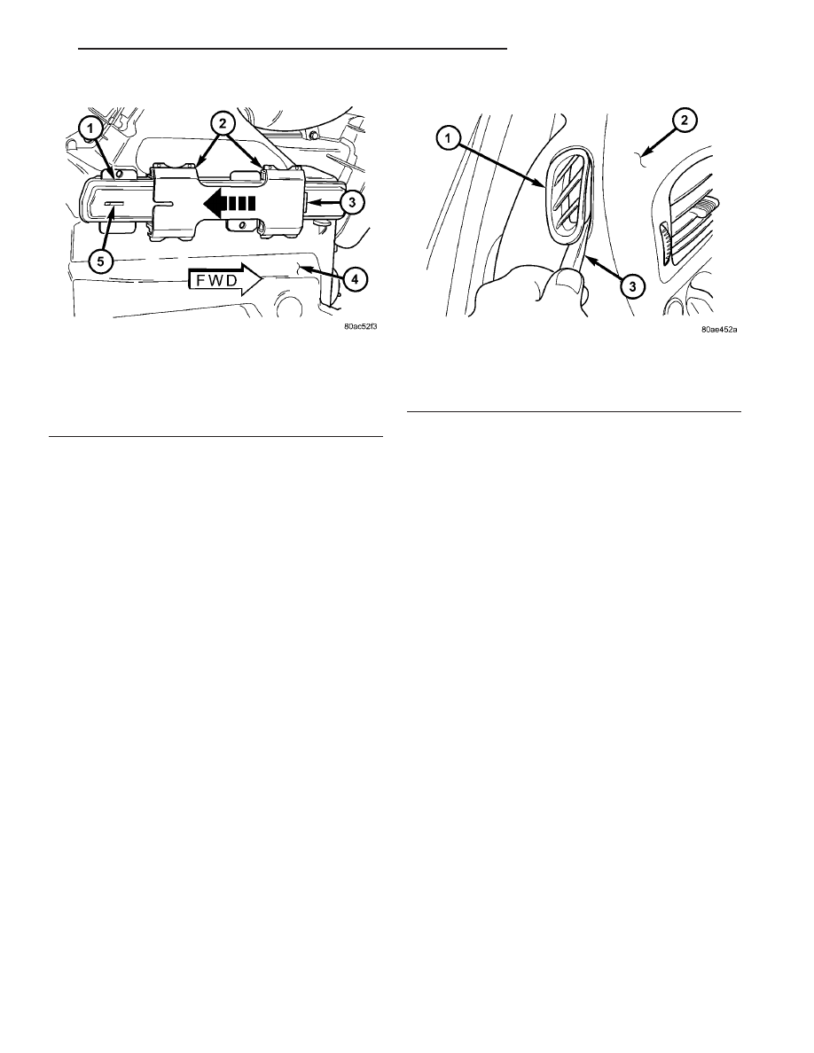
(1) Install the filter fully upward into the HVAC
housing through the air filter opening with the “Air-
flow” arrow oriented towards the center of the vehi-
cle.
(2) With the latch still positioned against its
opened stop, install the air filter door onto the lower
HVAC housing air filter opening.
(3) Slide the air filter door latch toward the front
of the vehicle until it contacts the closed stop on the
door.
AIR OUTLETS
REMOVAL
DEMISTER OUTLETS
(1) Using a trim stick C-4755 or equivalent, disen-
gage the retaining tabs that secure the outer perim-
eter of the demister outlet to the instrument panel
top pad and remove the outlet (Fig. 3).
CENTER BEZEL OUTLETS
WARNING: On vehicles equipped with airbags, dis-
able the airbag system before attempting any steer-
ing wheel, steering column, or instrument panel
component diagnosis or service. Disconnect and
isolate the battery negative (ground) cable, then
wait two minutes for the airbag system capacitor to
discharge before performing further diagnosis or
service. This is the only sure way to disable the air-
bag system. Failure to take the proper precautions
could result in accidental airbag deployment and
possible personal injury or death.
NOTE: Take the proper precautions to protect the
front face of the instrument panel center bezel from
cosmetic damage during this service procedure.
(1) Disconnect and isolate the negative battery
cable.
(2) Remove the center bezel from the instrument
panel and place it on a workbench (Refer to 23 -
BODY/INSTRUMENT
PANEL/INSTRUMENT
PANEL CENTER BEZEL - REMOVAL).
(3) If the vehicle is equipped with the automatic
temperature control (ATC) heating-A/C system, dis-
connect the infrared temperature sensor jumper har-
ness from the infrared temperature sensor located at
the bottom of the middle outlet (Fig. 4).
(4) Remove the three screws that secure the bot-
tom of the center bezel outlet housing to the center
bezel and disengage the retaining tabs at the top of
the housing.
(5) Remove the center bezel outlets and housing
from the center bezel as an assembly.
Fig. 2 Air Filter Door - Typical
1 - AIR FILTER DOOR
2 - LATCH
3 - CLOSED STOP
4 - LOWER FRONT HVAC HOUSING
5 - OPENED STOP
Fig. 3 Demister Outlet
1 - DEMISTER OUTLET
2 - INSTRUMENT PANEL TOP PAD
3 - TRIM STICK
RS
DISTRIBUTION - FRONT
24 - 45
AIR FILTER (Continued)