Chrysler RG Voyager. Manual - part 1149


  Index      Chrysler     Chrysler RG Voyager - service repair manual 2005 year


Search            


Content   ..  1147  1148  1149  1150   ..


Chrysler RG Voyager. Manual - part 1149


QUAD BUCKET SEAT SIDE
SHIELD/CUP HOLDER - FLAP
AND SPRING ASSEMBLY

REMOVAL

(1) Inspect the flap retaining tabs on cup holder

for damage (Fig. 103).

(2) If cracked or broken, replace quad bucket seat

side shield with cup holder. (Refer to 23 - BODY/
SEATS/SEAT SIDE SHIELD - REMOVAL).

(3) If flap retaining tabs are not damaged replace

flap and spring assembly.

INSTALLATION

(1) Ensure the spring is position into mounting tab

(Fig. 104).

(2) Hold flap and spring assembly in the horizon-

tal position and snap into cup holder flap retaining
tabs.

(3) Verify cup holder flap operation several times

to ensure proper operation. Flap should fold down-
ward with little effort and spring back to a horizontal
position when released.

BOTTOM OF SEAT CUSHION
PAN PANEL-THIRD ROW -
FOLD-IN-FLOOR

REMOVAL

(1) Fold the third row seat with back down.
(2) Remove handle from cushion.
(3) Using a trim tool, remove bottom side of the

cushion pan panel (Fig. 105).

INSTALLATION

(1) Place bottom side of the cushion pan panel into

position (Fig. 106).

(2) Press on back of cushion pan panel to seat the

fasteners.

(3) Install handle on cushion.
(4) Place seat in the up right position.

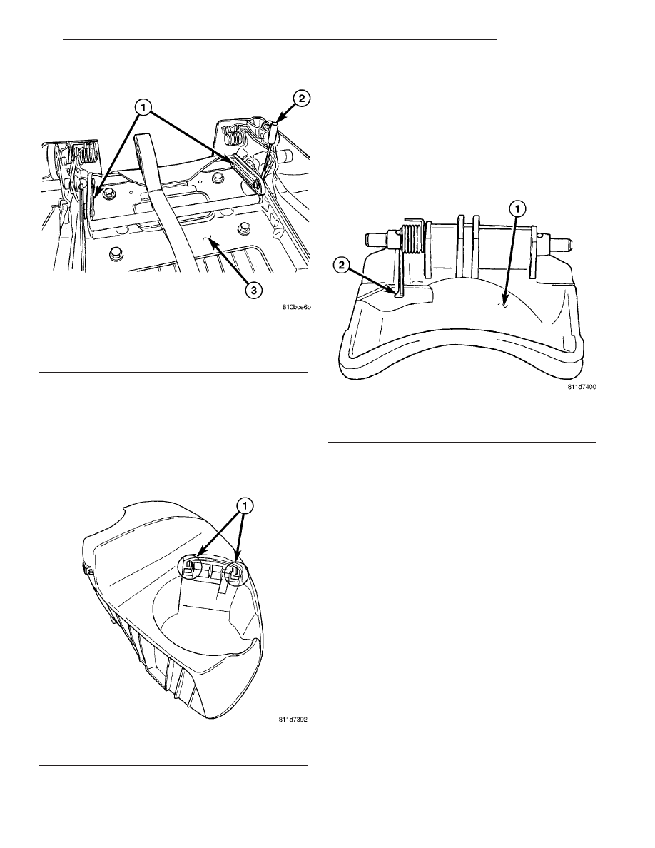
Fig. 102 SEAT RISER LATCH LOCKING LINK

1 - LATCH LOCKING LINK
2 - FLAT BLADED TOOL
3 - SEAT RISER

Fig. 103 CUP HOLDER FLAP RETAINING TABS

1 - FLAP RETAINING TABS

Fig. 104 FLAP AND SPRING ASSEMBLY

1 - CUP HOLDER FLAP
2 - SPRING IN MOUNTING TAB

RS

SEATS

23 - 175

SEAT RISER LATCH LOCKING LINK (Continued)

HEADREST SLEEVE - THIRD
ROW - FOLD-IN-FLOOR

REMOVAL

(1) Remove headrest (Fig. 107).
(2) Using a trim tool remove sleeve by prying

sleeve away from the seat back frame to unlock it
(Fig. 108)

(3) Pull headrest sleeve upward and out the top of

the seat back frame and remove from seat.

Fig. 105 THIRD ROW CUSHION PAN & COVER

Fig. 106 THIRD ROW CUSHION PAN & COVER

Fig. 107 HEADREST

1 - HEADREST
2 - DEPRESS TAB

Fig. 108 REMOVING HEADREST SLEEVES

1 - HEADREST SLEEVES
2 - TRIM TOOL

23 - 176

SEATS

RS

BOTTOM OF SEAT CUSHION PAN PANEL-THIRD ROW - FOLD-IN-FLOOR (Continued)

INSTALLATION

(1) Place headrest sleeve into position and push

downward until sleeve locks into position (Fig. 109).

(2) Install headrest (Fig. 107).

SEAT - THIRD ROW - FOLD-IN-
FLOOR

REMOVAL

(1) Fold third row seat into floor well.
(2) Using a trim stick, unclip anchor molding (Fig.

110).

(3) Remove third row seat attaching bolts (Fig.

111).

(4) Raise seats to the upright position.
(5) Remove the rear seat lower trim cover (Fig.

112).

(6) Remove rear attaching bolts (Fig. 113).
(7) Remove rear seat from vehicle.

Fig. 109 HEADREST SLEEVES

1 - SLEEVES

Fig. 110 ANCHOR MOLDING

1 - 2-WAY CLIPS INTO SEAT FRAME
2 - 4-WAY LOCATING PINS (2)
3 - FRONT SEAT ANCHOR MOLDING

Fig. 111 THIRD ROW SEATS

1 - ATTACHING BOLTS

RS

SEATS

23 - 177

HEADREST SLEEVE - THIRD ROW - FOLD-IN-FLOOR (Continued)

INSTALLATION

(1) Place rear seat into position (Fig. 114).

(2) Install rear attaching bolts to seat (Fig. 115).

Tighten bolts to 54 N·m (40 ft. lbs.) torque and follow
tightening sequence.

(3) Fold the rear seat into the floor well.
(4) Install attaching bolts (Fig. 116). Tighten bolts

to 54 N·m (40 ft. lbs.) torque.

(5) Place the rear seat lower trim cover into posi-

tion and press clips into the lock position (Fig. 117).

(6) Raise third row seat into upright position.

Fig. 112 REAR SEAT TRIM COVER

1 - PLASTIC NUTS ON WELD STUDS
2 - LOWER TRIM COVER

Fig. 113 THIRD ROW SEAT

1 - ATTACHING BOLTS

Fig. 114 THIRD ROW SEAT INSTALLED

1 - ALIGN SEAT BRACKETS WITH REAR EDGE OF TUB

Fig. 115 THIRD ROW SEAT

1 - ATTACHING BOLTS

23 - 178

SEATS

RS

SEAT - THIRD ROW - FOLD-IN-FLOOR (Continued)


Content   ..  1147  1148  1149  1150   ..