Content .. 1136 1137 1138 1139 ..
Chrysler RG Voyager. Manual - part 1138
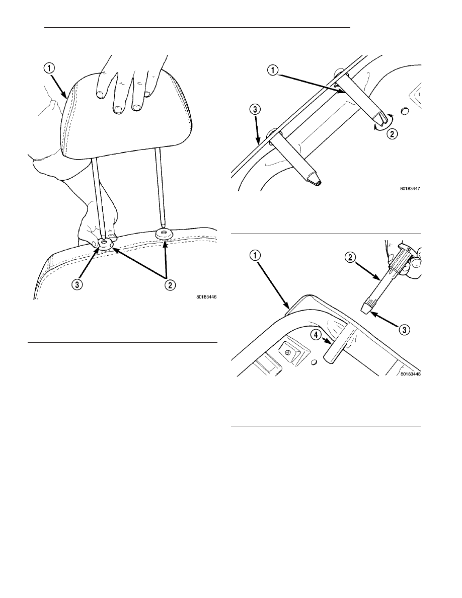
HEADREST SLEEVE
REMOVAL
(1) Remove head rest.
(2) Disengage closure attaching bottom of trim
cover together.
(3) Reach through opening at bottom of seat back.
(4) Pinch retainer barbs on end of head restraint
sleeve together (Fig. 10).
(5) Pull head restraint sleeve upward and out the
top of the seat back frame guide tube (Fig. 11).
INSTALLATION
(1) Insert head restraint sleeve into guide tube at
top of seat back.
(2) Push head restraint sleeve downward until
retainer clicks into lock position.
(3) Install seat back cover.
(4) Install head restraint.
RECLINER HANDLE
REMOVAL
(1) Remove
screw
holding
recliner
handle
to
recliner spline shaft (Fig. 12).
(2) Remove recliner handle from spline shaft.
INSTALLATION
(1) Place recliner handle in position on spline
shaft.
(2) Install screw to hold recliner handle to recliner
spline shaft (Fig. 12).
Fig. 9 HEAD RESTRAINT
1 - HEAD RESTRAINT
2 - SLEEVES
3 - LOCK BUTTON
Fig. 10 HEAD RESTRAINT SLEEVE RETAINER
1 - GUIDE TUBE
2 - PINCH RETAINER TO RELEASE
3 - SEAT BACK FRAME
Fig. 11 HEAD RESTRAINT SLEEVE
1 - SEAT BACK FRAME
2 - HEAD RESTRAINT SLEEVE
3 - RETAINER
4 - GUIDE TUBE
RS
SEATS
23 - 131
HEADREST (Continued)