Chrysler RG Voyager. Manual - part 1126


  Index      Chrysler     Chrysler RG Voyager - service repair manual 2005 year


Search            


Content   ..  1124  1125  1126  1127   ..


Chrysler RG Voyager. Manual - part 1126


LOWER STEERING COLUMN
COVER

REMOVAL

(1) Use trim stick to gently pry rt edge of steering

column cover from lower rt panel just enough to dis-
engage ’belt loops’ (Fig. 16).

(2) Pull lower steering column cover rearward to

release spring clips and remove from the vehicle.

(3) Remove the three screws attaching the end cap

to instrument panel.

(4) Pull end cap outward to release spring clips

and remove from the vehicle

INSTALLATION

(1) Place the end cap into position and push spring

clips into position (Fig. 16).

(2) Attach left side of lower steering column cover

first. Align locating ribs into left end cap and rock
cover to right side and align belt loops into position
into instrument lower right panel.

(3) Place the lower steering column cover into posi-

tion and push spring clips into position.

(4) Install the two screws attaching the lower

steering column cover to instrument panel.

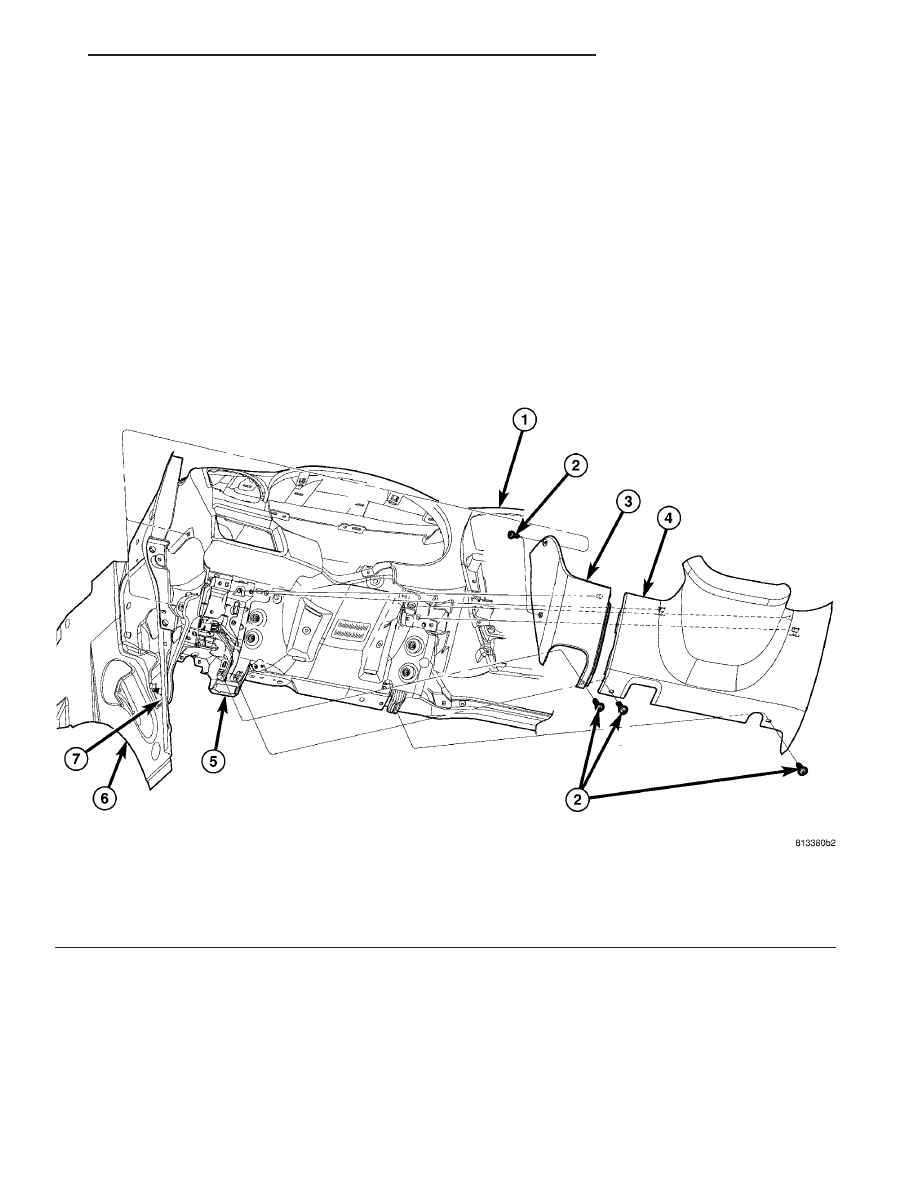
Fig. 16 STEERING COLUMN COVER AND END CAP

1 - INSTRUMENT PANEL UPPER AND LOWER PANEL
2 - ATTACHING SCREW(S)
3 - END CAP
4 - INSTRUMENT PANEL STEERING COLUMN COVER

5 - INSTRUMENT PANEL STEERING COLUMN COVER PLATE
6 - COWL PANEL
7 - COWL SIDE TAPPING PLATE

RS

INSTRUMENT PANEL

23 - 83

BLOCKER- INFLATABLE KNEE

REMOVAL

(1) Remove lower steering column cover (Refer to

23 - BODY/INSTRUMENT PANEL/STEERING COL-
UMN OPENING COVER - REMOVAL).

(2) Remove the park brake release handle link

from the park brake release handle.

(3) Disengage inflatable knee blocker wire connec-

tor from lower instrument and disconnect the wire
connector (Fig. 17).

(4) Remove screws attaching to instrument panel.
(5) Remove inflatable knee blocker from vehicle.

INSTALLATION

(1) Place inflatable knee blocker into position (Fig.

17).

(2) Connect inflatable knee blocker wire connector

and install inflatable knee blocker attaching screws.

(3) Install the steering column cover backing plate

into vehicle.

(4) Install park brake release handle link to park

brake release handle.

(5) Install the lower steering column cover (Refer

to 23 - BODY/INSTRUMENT PANEL/STEERING
COLUMN OPENING COVER - INSTALLATION).

Fig. 17 INFLATABLE KNEE BLOCKER

1 - INSTRUMENT PANEL COLUMN COVER PLATE
2 - COWL SIDE TAPPING PLATE
3 - LOWER INSTRUMENT PANEL REINFORCEMENT

4 - INFLATABLE KNEE BLOCKER WIRE CONNECTOR
5 - INFLATABLE KNEE BLOCKER
6 - KNEE LOCKER ATTACHING SCREWS

23 - 84

INSTRUMENT PANEL

RS

OVER STEERING COLUMN
COVER

REMOVAL

(1) Taking a firm grasp of the over steering col-

umn cover front edge, give a quick upward pulling
motion to disengage the cover from the instrument
panel (Fig. 18).

(2) Remove the over steering column cover from

the vehicle.

INSTALLATION

(1) Place the over steering column cover into posi-

tion over the retaining slots and firmly snap into
place (Fig. 18).

INSTRUMENT PANEL TOP PAD
ASSEMBLY

REMOVAL

(1) Remove the instrument cluster (Fig. 19). (Refer

to 8 - ELECTRICAL/INSTRUMENT CLUSTER -
REMOVAL)

(2) Remove the message center (Fig. 19). (Refer to

8 - ELECTRICAL/MESSAGE CENTER - REMOVAL)

(3) Remove the radio (Fig. 19). (Refer to 8 - ELEC-

TRICAL/AUDIO/RADIO - REMOVAL)

(4) Remove the headlamp switch (Fig. 19). (Refer

to 8 - ELECTRICAL/LAMPS/LIGHTING - EXTERI-
OR/HEADLAMP SWITCH - REMOVAL)

(5) Remove the lower console (Fig. 19). (Refer to 23

- BODY/INSTRUMENT PANEL/LOWER CONSOLE
- REMOVAL)

(6) Remove the lower panel. (Refer to 23 - BODY/

INSTRUMENT

PANEL/LOWER

INSTRUMENT

PANEL TRIM - REMOVAL)

(7) Remove the instrument panel assembly. (Refer

to 23 - BODY/INSTRUMENT PANEL/INSTRUMENT
PANEL ASSEMBLY - REMOVAL)

(8) Remove the instrument panel speakers.
(9) Remove the glove box light.
(10) Remove the two passenger air bag mounting

bolts (Fig. 20).

(11) Loosen the three passenger air bag support

bracket bolts to the hydro-form rail (Fig. 20).

(12) Remove the 16 screws along the upper edge of

the pad & panel assembly.

(13) Remove the 19 screws along the lower edge of

the pad & panel assembly.

(14) Remove the pad and panel assembly (Fig. 19).

Fig. 18 OVER STEERING COLUMN COVER

1 - INSTRUMENT PANEL OVER STEERING COLUMN COVER
2 - INSTRUMENT PANEL

Fig. 19 INSTRUMENT PANEL ASSEMBLY

1 - INSTRUMENT CLUSTER
2 - TOP COVER
3 - PAD AND PANEL ASSEMBLY
4 - LOWER CONSOLE
5 - LOWER PANEL
6 - RADIO
7 - HEADLAMP SWITCH

RS

INSTRUMENT PANEL

23 - 85

INSTALLATION

(1) Position the pan & panel assembly onto the

instrument panel support structure (Fig. 19).

(2) Install the 19 screws along the lower edge of

the pad & panel assembly (Fig. 19).

(3) Install the 16 screws along the upper edge of

the pad & panel assembly.

(4) Install and tighten the two passenger air bag

mounting screws (Fig. 20).

(5) Tighten the three passenger air bag support

bracket bolts to the hydro-form tube (Fig. 20).

(6) Install the glove box light.
(7) Install the instrument panel speakers.
(8) Install the instrument panel assembly. (Refer

to 23 - BODY/INSTRUMENT PANEL/INSTRUMENT
PANEL ASSEMBLY - INSTALLATION)

(9) Install the lower panel. (Refer to 23 - BODY/

INSTRUMENT

PANEL/LOWER

INSTRUMENT

PANEL TRIM - INSTALLATION)

(10) Install the lower console. (Refer to 23 - BODY/

INSTRUMENT

PANEL/LOWER

CONSOLE

-

INSTALLATION)

(11) Install the headlamp switch. (Refer to 8 -

ELECTRICAL/LAMPS/LIGHTING

-

EXTERIOR/

HEADLAMP SWITCH - INSTALLATION)

(12) Install the radio. (Refer to 8 - ELECTRICAL/

AUDIO/RADIO - INSTALLATION)

(13) Install the message center. (Refer to 8 -

ELECTRICAL/MESSAGE CENTER - INSTALLA-
TION)

(14) Install the instrument cluster. (Refer to 8 -

ELECTRICAL/INSTRUMENT CLUSTER - INSTAL-
LATION)

Fig. 20 AIRBAG MOUNTING HARDWARE

1 - AIR BAG SCREWS (2)
2 - ELECTRICAL CONNECTOR
3 - AIR BAG SUPPORT BRACKET BOLTS (3)
4 - HYDRO-FORM INSTRUMENT PANEL SUPPORT RAIL

23 - 86

INSTRUMENT PANEL

RS

INSTRUMENT PANEL TOP PAD ASSEMBLY (Continued)


Content   ..  1124  1125  1126  1127   ..