Chrysler RG Voyager. Manual - part 1110


  Index      Chrysler     Chrysler RG Voyager - service repair manual 2005 year


Search            


Content   ..  1108  1109  1110  1111   ..


Chrysler RG Voyager. Manual - part 1110


DOOR GLASS

REMOVAL

(1) Remove watershield. (Refer to 23 - BODY/

DOOR - FRONT/WATERSHIELD - REMOVAL)

(2) Remove inner belt molding. (Refer to 23 -

BODY/WEATHERSTRIP/SEALS/FDR INNER BELT
WEATHERSTRIP - REMOVAL)

(3) Position glass to gain access to front regulator

lift plate (Fig. 12)and rear regulator lift plate (Fig.
13) through front and rear access holes in door panel.

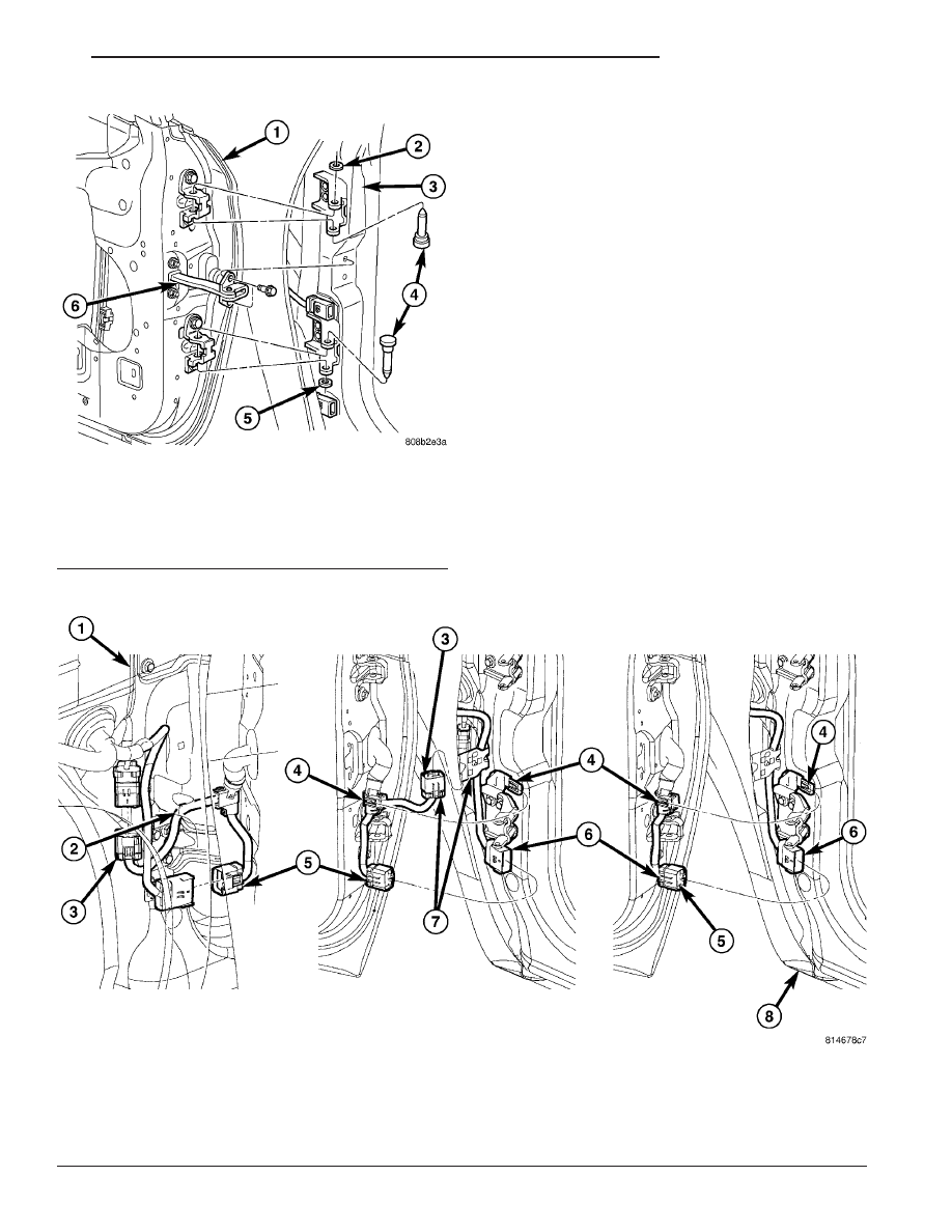
Fig. 11 FRONT DOOR WIRING TO BODY

1 - FENDER SIDE CONNECTION
2 - ROUTE 10-WAY UPPER DOOR WIRE CONNECTOR
THOROUGH FENDER BRACKET PRIOR TO DOOR BEING
INSTALLED
3 - 10-WAY WIRE CONNECTOR
4 - DOOR HARNESS PLASTIC TEE SLIDE ON FEATURE TO
UPPER BAYONET CLIP

5 - LOWER 10-WAY CONNECTOR
6 - 10-WAY CONNECTOR ON THE COWL SIDE PANEL
7 - WIRE HARNESS MUST BE ROUTED UNDER FENDER
BRACKET
8 - LOW LINE VEHICLE ONLY

Fig. 10 FRONT DOOR - HINGE PINS

1 - FRONT DOOR
2 - CLIP
3 - A-PILLAR
4 - HINGE PIN
5 - CLIP
6 - DOOR CHECK STRAP

RS

DOOR - FRONT

23 - 19

DOOR (Continued)

(4) Loosen two screws on regulator clamping glass

(Fig. 13).

(5) Remove glass from regulator lift plates.
(6) Disengage glass from glass run weatherstrip.
(7) Insert front of glass between glass run channel

and outer door panel.

(8) Lift glass upward and out of exterior side of

the opening at top of door (Fig. 14).

(9) Remove glass from vehicle.

INSTALLATION

(1) Ensure clamp opening is set to 6 mm (0.2 in.)

for the front and rear glass liftplate (Fig. 15) and
(Fig. 16).

(2) Place glass in window opening with front

inserted between run channel and outer door panel
(Fig. 17).

(3) Lower glass downward into door.
(4) Insert ends of glass into glass run weatherstrip

channels at front and rear of door.

(5) Place glass in position on regulator glass

clamps.

Fig. 12 FRONT GLASS LIFTPLATE

Fig. 13 REAR GLASS CLIPS

1 - DOOR GLASS
2 - REGULATOR GLASS CLAMP ASSEMBLY
3 - GLASS LIFT PLATE

Fig. 14 FRONT DOOR GLASS

1 - DOOR GLASS
2 - FRONT DOOR
3 - GLASS RUN CHANNEL

Fig. 15 FRONT GLASS LIFTPLATE

23 - 20

DOOR - FRONT

RS

DOOR GLASS (Continued)

(6) Roll glass up to level to tighten the two glass

clamp fasteners. Tighten fasteners to 12 N·m (105 in.
lbs.) torque.

(7) Install inner belt molding. (Refer to 23 - BODY/

WEATHERSTRIP/SEALS/FRONT

DOOR

INNER

BELT MOLDING - INSTALLATION)

(8) Verify door glass operation and fit.

(9) Install watershield. (Refer to 23 - BODY/DOOR

- FRONT/WATERSHIELD - INSTALLATION)

FRAME CLOSEOUT MOLDING

REMOVAL – A-PILLAR-HEADER, OR B-PILLAR

(1) Roll door glass down.
(2) Using a hook tool, pull front door frame close-

out molding from window frame channel.

(3) Remove closeout molding from vehicle.

INSTALLATION – A-PILLAR-HEADER, OR
B-PILLAR

(1) Position closeout molding in window frame.
(2) Insert closeout molding into window frame

channel starting at the corners and working inward.

(3) Verify door glass operation.

HINGE

REMOVAL

(1) Release front door latch and open door.
(2) Mark hinge foot print on both door and pillar

to aid when installing door.

(3) Support door on suitable lifting device.
(4) Remove bolts attaching front door to door

hinge.

(5) Remove bolts attaching hinge to pillar.
(6) Remove door hinge from vehicle.

INSTALLATION

CAUTION: When installing a new hinge, make sure
that the head of each hinge pin is fully seated into
the door hinge. Also, remove the plastic shipping
clip and replace it with the correct metal retaining
clip once the hinge pin is seated.

(1) Paint hinge prior to installation, if necessary.
(2) Position door to vehicle. Verify net pierce nub-

bin is engaged if reusing original hinges. Applies to
body half of hinge only.

(3) Install bolts attaching hinge to pillar. Tighten

bolts to 34 N·m (25 ft. lbs.).

(4) Install bolts attaching front door to door hinge.

Tighten bolts to 34 N·m (25 ft. lbs.).

(5) Align door to achieve equal spacing to sur-

rounding body panels. Panels should be flush across
all gaps.

(6) Verify door alignment and operation. Adjust as

necessary.

Fig. 16 REAR GLASS CLIPS

1 - DOOR GLASS
2 - REGULATOR GLASS CLAMP ASSEMBLY
3 - GLASS LIFT PLATE

Fig. 17 FRONT DOOR GLASS

1 - DOOR GLASS
2 - FRONT DOOR
3 - GLASS RUN CHANNEL

RS

DOOR - FRONT

23 - 21

DOOR GLASS (Continued)

LATCH

REMOVAL

(1) Roll door glass up.
(2) Remove front door trim panel. (Refer to 23 -

BODY/DOOR - FRONT/TRIM PANEL - REMOVAL)

(3) Remove watershield as necessary to gain access

to the outside door handle.

(4) Through access hole at rear of inner door

panel, disconnect wire connector from power door
lock motor, if equipped.

(5) Disengage clips holding linkage to door latch

(Fig. 18).

(6) Remove linkages from door latch.
(7) Remove screws attaching door latch to door end

frame (Fig. 19).

(8) Remove door latch from door.

INSTALLATION

NOTE: The screws attaching the door latch to the
door end frame have nylon patches on the threads.
All screws must be replaced when the latch has
been removed.

(1) Insert inside handle latch link to door latch

and engage clip (Fig. 18).

(2) Place door latch in position on door end frame.

(3) Install screws attaching door latch to door end

frame. Tighten screws to 10 N·m (90 in. lbs.) torque
(Fig. 19).

(4) Insert other linkages to door latch and engage

clips.

(5) Connect wire connector into power door lock

motor, if equipped.

(6) Insert a hex wrench through the elongated hole

located in the door shut face above the latch.

(7) Loosen allen head screw.
(8) Pull outward on the outside door handle and

release.

(9) Tighten allen head screw.
(10) Verify door latch and power door lock opera-

tion.

(11) Install watershield and front door trim panel.

LATCH STRIKER

REMOVAL

(1) Mark outline of door striker on B-pillar to aid

in installation.

(2) Remove screws attaching door latch striker to

B-pillar (Fig. 20).

(3) Remove door latch striker from vehicle.
(4) Retrieve any shims found between latch striker

and B-pillar.

INSTALLATION

(1) Position latch striker and any shims retrieved

on vehicle.

(2) Loosely install screws attaching latch striker to

B-pillar.

(3) Align latch striker to outline on B-pillar made

previously.

Fig. 18 LATCH ASSEMBLY

1 - OUTSIDE HANDLE TO LATCH LINK
2 - KEY CYLINDER TO LATCH LINK
3 - LATCH ASSEMBLY
4 - INSIDE HANDLE LINK AND SLEEVE
5 - LOCK KNOB LINK

Fig. 19 FRONT DOOR LATCH

1 - FRONT DOOR
2 - LATCH ASSEMBLY
3 - INSIDE HANDLE LINK

23 - 22

DOOR - FRONT

RS


Content   ..  1108  1109  1110  1111   ..