Chrysler PT Cruiser. Manual - part 990


  Index      Chrysler     Chrysler PT Cruiser - service repair manual 2005 year


Search            


Content   ..  988  989  990  991   ..


Chrysler PT Cruiser. Manual - part 990


INSTALLATION

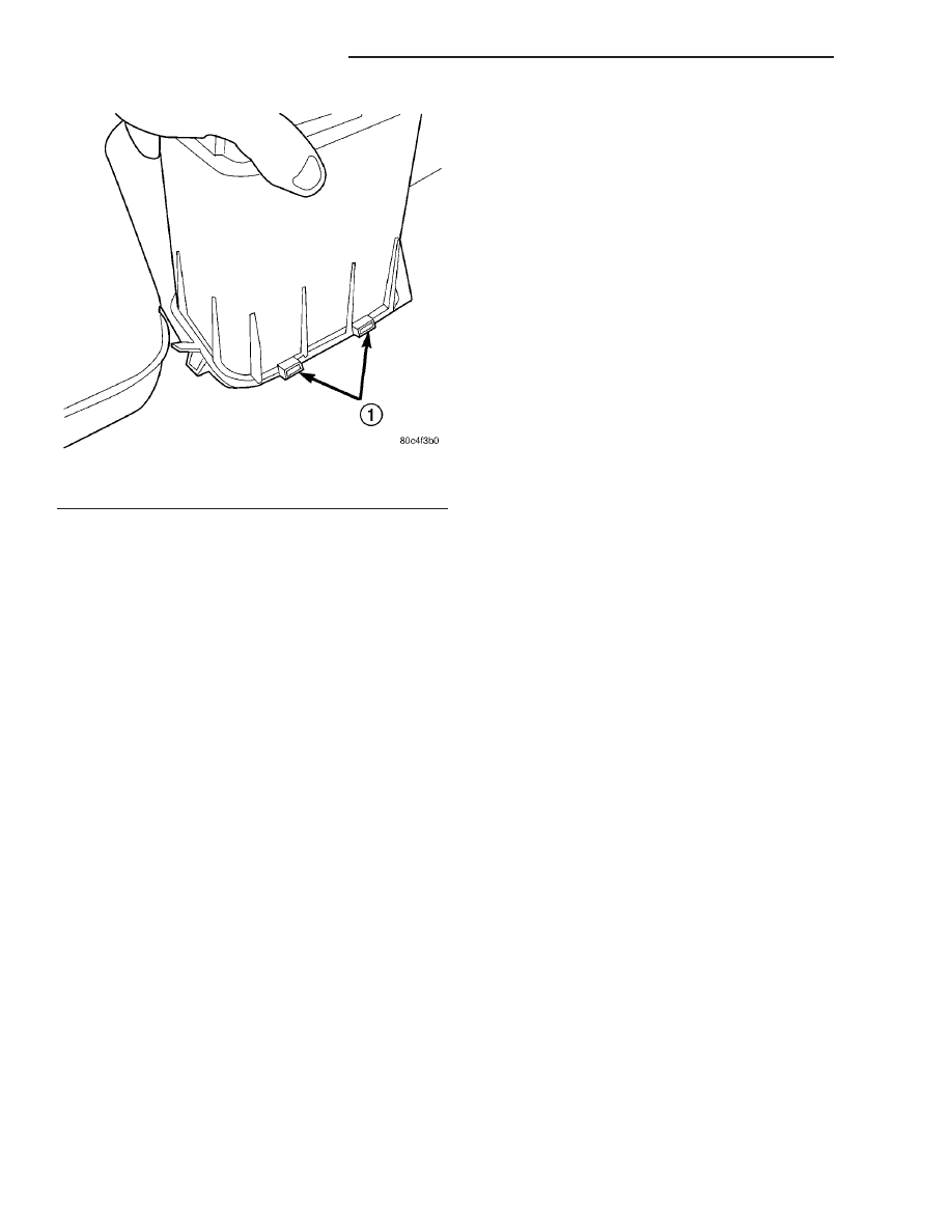
(1) Install EVAP canister over bracket tabs (Fig.

19).

(2) Push canister back and into the bracket until

the spring clips snap over the edge of the canister
(Fig. 18).

(3) Install the push pin through the EVAP canister

and the bracket and into the fuel tank (Fig. 17).

(4) Install hoses and lines.
(5) Install the fuel tank and EVAP system, refer to

the Fuel Tank removal/installation section in the
Fuel Delivery section.

(6) Lower vehicle.
(7) Install the negative battery cable.
(8) Install the air cleaner lid, connect the inlet air

temperature sensor and makeup air hose.

(9) Fill fuel tank. Use the DRBIII

t scan tool to

pressurize the fuel system. Check for leaks.

Fig. 19 Bracket Tabs

1 - TABS

25 - 20

EVAPORATIVE EMISSIONS

PT

VAPOR CANISTER (Continued)

ON-BOARD DIAGNOSTICS

TABLE OF CONTENTS

page

page

TASK MANAGER

DESCRIPTION

. . . . . . . . . . . . . . . . . . . . . . . . . 21

OPERATION

. . . . . . . . . . . . . . . . . . . . . . . . . . . 21

TASK MANAGER

DESCRIPTION

The PCM is responsible for efficiently coordinating

the operation of all the emissions-related compo-
nents. The PCM is also responsible for determining if
the diagnostic systems are operating properly. The
software designed to carry out these responsibilities
is call the “Task Manager”.

OPERATION

The Task Manager determines when tests happen

and when functions occur. Many of the diagnostic
steps required by OBD II must be performed under
specific operating conditions. The Task Manager soft-
ware organizes and prioritizes the diagnostic proce-
dures. The job of the Task Manager is to determine if
conditions are appropriate for tests to be run, moni-
tor the parameters for a trip for each test, and record
the results of the test. Following are the responsibil-
ities of the Task Manager software:

• Test Sequence

• MIL Illumination

• Diagnostic Trouble Codes (DTCs)

• Trip Indicator

• Freeze Frame Data Storage

• Similar Conditions Window

Test Sequence

In many instances, emissions systems must fail

diagnostic tests more than once before the PCM illu-
minates the MIL. These tests are known as ’two trip
monitors.’ Other tests that turn the MIL lamp on
after a single failure are known as ’one trip moni-
tors.’ A trip is defined as ’start the vehicle and oper-
ate it to meet the criteria necessary to run the given
monitor.’

Many of the diagnostic tests must be performed

under certain operating conditions. However, there
are times when tests cannot be run because another
test is in progress (conflict), another test has failed
(pending) or the Task Manager has set a fault that
may cause a failure of the test (suspend).

• Pending

Under some situations the Task Manager will not
run a monitor if the MIL is illuminated and a fault is
stored from another monitor. In these situations, the
Task Manager postpones monitors pending resolu-
tion of the original fault. The Task Manager does not
run the test until the problem is remedied.
For example, when the MIL is illuminated for an
Oxygen Sensor fault, the Task Manager does not run
the Catalyst Monitor until the Oxygen Sensor fault is
remedied. Since the Catalyst Monitor is based on sig-
nals from the Oxygen Sensor, running the test would
produce inaccurate results.

• Conflict

There are situations when the Task Manager does
not run a test if another monitor is in progress. In
these situations, the effects of another monitor run-
ning could result in an erroneous failure. If this con-
flict 
is present, the monitor is not run until the
conflicting condition passes. Most likely the monitor
will run later after the conflicting monitor has
passed.
For example, if the Fuel System Monitor is in
progress, the Task Manager does not run the catalyst
Monitor. Since both tests monitor changes in air/fuel
ratio and adaptive fuel compensation, the monitors
will conflict with each other.

• Suspend

Occasionally the Task Manager may not allow a two
trip fault to mature. The Task Manager will sus-
pend 
the maturing of a fault if a condition exists
that may induce an erroneous failure. This prevents
illuminating the MIL for the wrong fault and allows
more precise diagnosis.
For example, if the PCM is storing a one trip fault
for the Oxygen Sensor and the catalyst monitor, the
Task Manager may still run the catalyst Monitor but
will suspend the results until the Oxygen Sensor
Monitor either passes or fails. At that point the Task
Manager can determine if the catalyst system is
actually failing or if an Oxygen Sensor is failing.

PT

ON-BOARD DIAGNOSTICS

25 - 21

MIL Illumination

The PCM Task Manager carries out the illumina-

tion of the MIL. The Task Manager triggers MIL illu-
mination upon test failure, depending on monitor
failure criteria.

The Task Manager Screen shows both a Requested

MIL state and an Actual MIL state. When the MIL is
illuminated upon completion of a test for a good trip,
the Requested MIL state changes to OFF. However,
the MIL remains illuminated until the next key
cycle. (On some vehicles, the MIL will actually turn
OFF during the thirdgood trip) During the key cycle
for the third good trip, the Requested MIL state is
OFF, while the Actual MIL state is ON. After the
next key cycle, the MIL is not illuminated and both
MIL states read OFF.

Diagnostic Trouble Codes (DTCs)

With OBD II, different DTC faults have different

priorities according to regulations. As a result, the
priorities determine MIL illumination and DTC era-
sure. DTCs are entered according to individual prior-
ity. DTCs with a higher priority overwrite lower
priority DTCs.

Priorities

• Priority 0 —Non-emissions related trouble codes.

• Priority 1 — One trip failure of a two trip fault

for non-fuel system and non-misfire. (MIL Off)

• Priority 2 — One trip failure of a two trip fault

for fuel system (rich/lean) or misfire. (MIL Off)

• Priority 3 — Two trip failure for a non-fuel sys-

tem and non-misfire or matured one trip comprehen-
sive component fault. (MIL On)

• Priority 4 — Two trip failure or matured fault

for fuel system (rich/lean) and misfire or one trip cat-
alyst damaging misfire. Catalyst damage misfire is a
2 trip MIL. The MIL flashes on the first trip when
catalyst damage misfire levels are present. (MIL On)

Non-emissions related failures have no priority.

One trip failures of two trip faults have low priority.
Two trip failures or matured faults have higher pri-
ority. One and two trip failures of fuel system and
misfire monitor take precedence over non-fuel system
and non-misfire failures.

DTC Self Erasure

With one trip components or systems, the MIL is

illuminated upon test failure and DTCs are stored.

Two trip monitors are components requiring failure

in two consecutive trips for MIL illumination. Upon
failure of the first test, the Task Manager enters a
maturing code. If the component fails the test for a
second time the code matures and a DTC is set.

After three good trips the MIL is extinguished and

the Task Manager automatically switches the trip

counter to a warm-up cycle counter. DTCs are auto-
matically erased following 40 warm-up cycles if the
component does not fail again.

For misfire and fuel system monitors, the compo-

nent must pass the test under a Similar Conditions
Window in order to record a good trip. A Similar Con-
ditions Window is when engine RPM is within ±375
RPM and load is within ±20% of when the fault
occurred.

NOTE: It is important to understand that a compo-
nent does not have to fail under a similar window of
operation to mature. It must pass the test under a
Similar Conditions Window when it failed to record
a Good Trip for DTC erasure for misfire and fuel
system monitors.

DTCs can be erased anytime with a DRBIII

t.

Erasing the DTC with the DRBIII

t erases all OBD II

information. The DRBIII

t automatically displays a

warning that erasing the DTC will also erase all
OBD II monitor data. This includes all counter infor-
mation for warm-up cycles, trips and Freeze Frame.

Trip Indicator

The Trip is essential for running monitors and

extinguishing the MIL. In OBD II terms, a trip is a
set of vehicle operating conditions that must be met
for a specific monitor to run. All trips begin with a
key cycle.

Good Trip
The Good Trip counters are as follows:
• Global Good Trip

• Fuel System Good Trip

• Misfire Good Trip

• Alternate Good Trip (appears as a Global Good

Trip on DRBIII

t)

• Comprehensive Components

• Major Monitor

• Warm-Up Cycles
Global Good Trip
To increment a Global Good Trip, the Oxygen sen-

sor and Catalyst efficiency monitors must have run
and passed, and 2 minutes of engine run time.

Fuel System Good Trip
To count a good trip (three required) and turn off

the MIL, the following conditions must occur:

• Engine in closed loop

• Operating in Similar Conditions Window

• Short Term multiplied by Long Term less than

threshold

• Less than threshold for a predetermined time
If all of the previous criteria are met, the PCM will

count a good trip (three required) and turn off the
MIL.

25 - 22

ON-BOARD DIAGNOSTICS

PT

TASK MANAGER (Continued)

Misfire Good Trip
If the following conditions are met the PCM will

count one good trip (three required) in order to turn
off the MIL:

• Operating in Similar Condition Window

• 1000 engine revolutions with no misfire
Alternate Good Trip
Alternate Good Trips are used in place of Global

Good Trips for Comprehensive Components and
Major Monitors. If the Task Manager cannot run a
Global Good Trip because a component fault is stop-
ping the monitor from running, it will attempt to
count an Alternate Good Trip.

The Task Manager counts an Alternate Good Trip

for Comprehensive components when the following
conditions are met:

• Two minutes of engine run time, idle or driving

• No other faults occur
The Task Manager counts an Alternate Good Trip

for a Major Monitor when the monitor runs and
passes. Only the Major Monitor that failed needs to
pass to count an Alternate Good Trip.

Warm-Up Cycles
Once the MIL has been extinguished by the Good

Trip Counter, the PCM automatically switches to a
Warm-Up Cycle Counter that can be viewed on the
DRBIII

t. Warm-Up Cycles are used to erase DTCs

and Freeze Frames. Forty Warm-Up cycles must
occur in order for the PCM to self-erase a DTC and
Freeze Frame. A Warm-Up Cycle is defined as fol-
lows:

• Engine coolant temperature must start below

and rise above 160° F

• Engine coolant temperature must rise by 40° F

• No further faults occur

Freeze Frame Data Storage

Once a failure occurs, the Task Manager records

several engine operating conditions and stores it in a
Freeze Frame. The Freeze Frame is considered one
frame of information taken by an on-board data
recorder. When a fault occurs, the PCM stores the
input data from various sensors so that technicians
can determine under what vehicle operating condi-
tions the failure occurred.

The data stored in Freeze Frame is usually

recorded when a system fails the first time for two
trip faults. Freeze Frame data will only be overwrit-
ten by a different fault with a higher priority.

CAUTION: Erasing DTCs, either with the DRBIII

T

; or

by disconnecting the battery, also clears all Freeze
Frame data.

Similar Conditions Window

The Similar Conditions Window displays informa-

tion about engine operation during a monitor. Abso-
lute MAP (engine load) and Engine RPM are stored
in this window when a failure occurs. There are two
different Similar conditions Windows: Fuel System
and Misfire.

FUEL SYSTEM
• Fuel System Similar Conditions Window 

An indicator that ’Absolute MAP When Fuel Sys Fail’
and ’RPM When Fuel Sys Failed’ are all in the same
range when the failure occurred. Indicated by switch-
ing from ’NO’ to ’YES’.

• Absolute MAP When Fuel Sys Fail — The

stored MAP reading at the time of failure. Informs
the user at what engine load the failure occurred.

• Absolute MAP — A live reading of engine load

to aid the user in accessing the Similar Conditions
Window.

• RPM When Fuel Sys Fail — The stored RPM

reading at the time of failure. Informs the user at
what engine RPM the failure occurred.

• Engine RPM — A live reading of engine RPM

to aid the user in accessing the Similar Conditions
Window.

• Adaptive Memory Factor — The PCM utilizes

both Short Term Compensation and Long Term Adap-
tive to calculate the Adaptive Memory Factor for
total fuel correction.

• Upstream O2S Volts — A live reading of the

Oxygen Sensor to indicate its performance. For
example, stuck lean, stuck rich, etc.

• SCW Time in Window (Similar Conditions

Window Time in Window) — A timer used by the
PCM that indicates that, after all Similar Conditions
have been met, if there has been enough good engine
running time in the SCW without failure detected.
This timer is used to increment a Good Trip.

• Fuel System Good Trip Counter — A Trip

Counter used to turn OFF the MIL for Fuel System
DTCs. To increment a Fuel System Good Trip, the
engine must be in the Similar Conditions Window,
Adaptive Memory Factor must be less than cali-
brated threshold and the Adaptive Memory Factor
must stay below that threshold for a calibrated
amount of time.

• Test Done This Trip — Indicates that the

monitor has already been run and completed during
the current trip.

MISFIRE
• Same Misfire Warm-Up State — Indicates if

the misfire occurred when the engine was warmed up
(above 160° F).

PT

ON-BOARD DIAGNOSTICS

25 - 23

TASK MANAGER (Continued)


Content   ..  988  989  990  991   ..