Chrysler PT Cruiser. Manual - part 911
 

  Index      Chrysler     Chrysler PT Cruiser - service repair manual 2005 year


Search            


Content   ..  909  910  911  912   ..


Chrysler PT Cruiser. Manual - part 911


CLUSTER BEZEL

REMOVAL

(1) Open hood.
(2) Disconnect and isolate the battery negative

cable (Fig. 2).

(3) Remove the instrument panel top cover. (Refer

to 23 - BODY/INSTRUMENT PANEL/INSTRUMENT
PANEL TOP COVER - REMOVAL)

(4) Remove the steering column cover. (Refer to 23

- BODY/INSTRUMENT PANEL/STEERING COL-
UMN OPENING COVER - REMOVAL)

(5) Remove the left instrument panel end cap.

(Refer to 23 - BODY/INSTRUMENT PANEL/IN-
STRUMENT PANEL END CAP - REMOVAL)

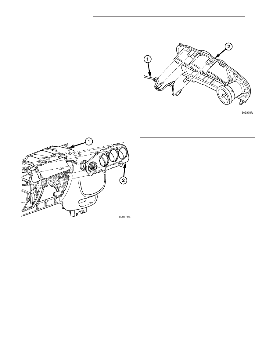
(6) Grab the sides of the instrument cluster bezel

and gently give a quick pull to unsnap the cluster
bezel (Fig. 6).

(7) Disconnect the turn signal lamps from the

instrument cluster bezel (Fig. 7).

(8) Remove bezel from vehicle.
If replacing the instrument cluster bezel, the A/C

outlet housing assembly must be transferred to the
new bezel. Refer to Removal and Installation, A/C
Outlet Housing Assembly in this section.

INSTALLATION

(1) Insert turn signal lamps into the instrument

cluster bezel (Fig. 7).

(2) Position instrument cluster bezel in position

making sure all fasteners are lined up with their
respective slots.

(3) Gently, but forcefully, snap the instrument

cluster bezel into place (Fig. 6).

(4) Install the left instrument panel end cap.

(Refer to 23 - BODY/INSTRUMENT PANEL/IN-
STRUMENT PANEL END CAP - INSTALLATION)

(5) Install the steering column cover. (Refer to 23 -

BODY/INSTRUMENT PANEL/STEERING COLUMN
OPENING COVER - INSTALLATION)

(6) Install the instrument panel top cover. (Refer

to 23 - BODY/INSTRUMENT PANEL/INSTRUMENT
PANEL TOP COVER - INSTALLATION)

(7) Connect the battery negative cable (Fig. 2).
(8) Close the hood.
(9) Verify vehicle and system operation.

Fig. 6 INSTRUMENT CLUSTER BEZEL

1 - INSTRUMENT PANEL
2 - CLUSTER BEZEL

Fig. 7 TURN SIGNAL INDICATOR LAMPS

1 -CLUSTER BEZEL
2 - TURN SIGNAL LAMPS AND WIRE HARNESS

23 - 102

INSTRUMENT PANEL

PT

GLOVE BOX

REMOVAL

(1) Open front passenger door.
(2) Open glove box door, push in on box/bin sides

to release the glove box (Fig. 8).

(3) Allow the glove box to drop down. With a firm

quick motion, twist the glove box assembly off the
hinge pins.

INSTALLATION

(1) Place glove box assembly in position and make

sure the orientation of the hinge is correct and rotate
glove box assembly hinge into place (Fig. 9).

(2) Lift glove box assembly up, push in on the box/

bin sides to allow the glove box to pass by the instru-
ment panel (Fig. 8).

(3) Close glove box.
(4) Shut passenger door.

GLOVE BOX LATCH

REMOVAL

(1) Open front passenger door.
(2) Remove glove box assembly. Refer to Removal

and Installation, Glove Box Assembly in this section.

(3) With glove box assembly on bench, remove

eleven glove box assembly screws (Fig. 10).

INSTALLATION

(1) Reassemble glove box assembly (Fig. 10) and

(Fig. 11).

(2) Install glove box assembly. Refer to Removal

and Installation, Glove Box Assembly in this section.

(3) Close passenger door.

Fig. 8 GLOVE BOX

1 - INSTRUMENT PANEL PASSENGER AIRBAG COVER
2 - GLOVE BOX

Fig. 9 GLOVE BOX ASSEMBLY HINGE

Fig. 10 GLOVE BOX ASSEMBLY SCREWS

PT

INSTRUMENT PANEL

23 - 103

GLOVE BOX LOCK CYLINDER

REMOVAL

(1) Open passenger door.
(2) Remove and disassemble glove box assembly.

Refer to Removal and Installation, Glove Box Door/
Bin/Latch in this section.

(3) Insert key into glove box lock cylinder. Using a

small pocket screwdriver or equivalent, push in on
retaining tab as you turn the lock cylinder 90° and
pull out lock cylinder (Fig. 12) and (Fig. 13).

INSTALLATION

(1) Insert key into lock cylinder.
(2) Push lock cylinder into latch and turn to

straight up and down position.

(3) Remove key.
(4) Reassemble glove box assembly and reinstall

into vehicle. Refer to Removal and Installation, Glove
Box Door/Bin/Latch in this section.

Fig. 11 GLOVE BOX ASSEMBLY BREAKDOWN

1 - LATCH
2 - INNER DOOR
3 - OUTER DOOR
4 - BOX

Fig. 12 GLOVE BOX LOCK CYLINDER RELEASE

TAB LOCATION

Fig. 13 GLOVE BOX LOCK CYLINDER

23 - 104

INSTRUMENT PANEL

PT

GLOVE BOX LATCH (Continued)

INSTRUMENT PANEL
ASSEMBLY

REMOVAL

(1) Open hood.
(2) Disconnect and isolate the battery negative

cable (Fig. 14).

(3) Remove the instrument panel top cover (Fig.

15).

(a) Using a trim stick (special tool #C-4755) or

equivalent, gently pry off the left and right A-pillar
trim.

(b) Using a trim stick or equivalent, gently pry

out the front power window switch from the instru-
ment panel center bezel. Disconnect the harness
connector and remove.

(c) Remove the one center bezel retaining screw.
(d) Pull off the HVAC control knobs.
(e) Using a trim stick or equivalent, gently pry

off the center bezel and remove.

(f) Remove the two top cover retaining screws.
(g) Gently pull rearward on the top cover and

unlatch it from the instrument panel and remove.
(4) Remove two screws retaining HVAC control.
(5) Pull the HVAC control out of instrument panel,

disconnect the one wiring connector, the one vacuum
harness connector, and disconnect the two control
cables. Remove HVAC control from vehicle.

(6) Remove the two retaining screws to the upper

and lower steering column shrouds.

(7) Gently pry the upper and lower shrouds apart

and remove from steering column.

(8) Remove the steering column cover. Pull top

down, lower to floor and twist steering column cover
off instrument panel hinge pins.

(9) Disconnect the steering column wire connec-

tors:

(a) Ignition Switch
(b) Multi-Function Switch
(c) Clockspring

CAUTION: Lock the steering wheel in the straight
ahead position. This will prevent clockspring dam-
age when the steering wheel rotates freely.

(10) Remove steering column:

(a) Remove the steering column pinch bolt at the

base of the lower coupler.

(b) Remove the four retaining nuts to the steer-

ing column.

(c) Pull column rearward and out of instrument

panel opening and remove from vehicle.
(11) Remove the two brake pedal support bracket,

instrument panel retaining bolts (Fig. 16).

(12) Remove two screws to the left instrument

panel end cap.

(13) Pull the left end cap rearward to unsnap and

remove it from vehicle.

(14) Disconnect the five left side wiring connectors:

(a) Data Link Connector
(b) Two main instrument panel connectors.
(c) Brake Switch
(d) Left Side Body Harness
(e) Left Door Harness

Fig. 14 BATTERY NEGATIVE CABLE REMOVAL/

INSTALLATION

PT

INSTRUMENT PANEL

23 - 105


Content   ..  909  910  911  912   ..