Chrysler PT Cruiser. Manual - part 901


  Index      Chrysler     Chrysler PT Cruiser - service repair manual 2005 year


Search            


Content   ..  899  900  901  902   ..


Chrysler PT Cruiser. Manual - part 901


INSTALLATION

INSTALLATION

(1) Install door handle latch link to handle.
(2) Position door handle into door (Fig. 26).
(3) Install fasteners attaching door handle to outer

door panel.

(4) Connect lock and latch rods to door latch.
(5) Install door trim panel and water dam.

INSTALLATION - PT-27 ONLY

(1) Install door handle latch link to handle.
(2) Position door handle into door (Fig. 27).
(3) Install fasteners attaching door handle to outer

door panel.

(4) Connect lock and latch rods to door latch.
(5) Install door trim panel and water dam.

FRONT DOOR HINGE

REMOVAL

REMOVAL

(1) Open and support door on a suitable lifting

device.

(2) Remove bolts attaching door check strap to

lower A-pillar for greater access, if necessary (Fig. 4).

(3) Mark position of hinge on both the door end

frame and lower A-pillar to ease installation.

(4) Remove bolts attaching hinge to door end

frame.

(5) Remove bolts attaching hinge to lower A-pillar.
(6) Remove door hinge from vehicle.

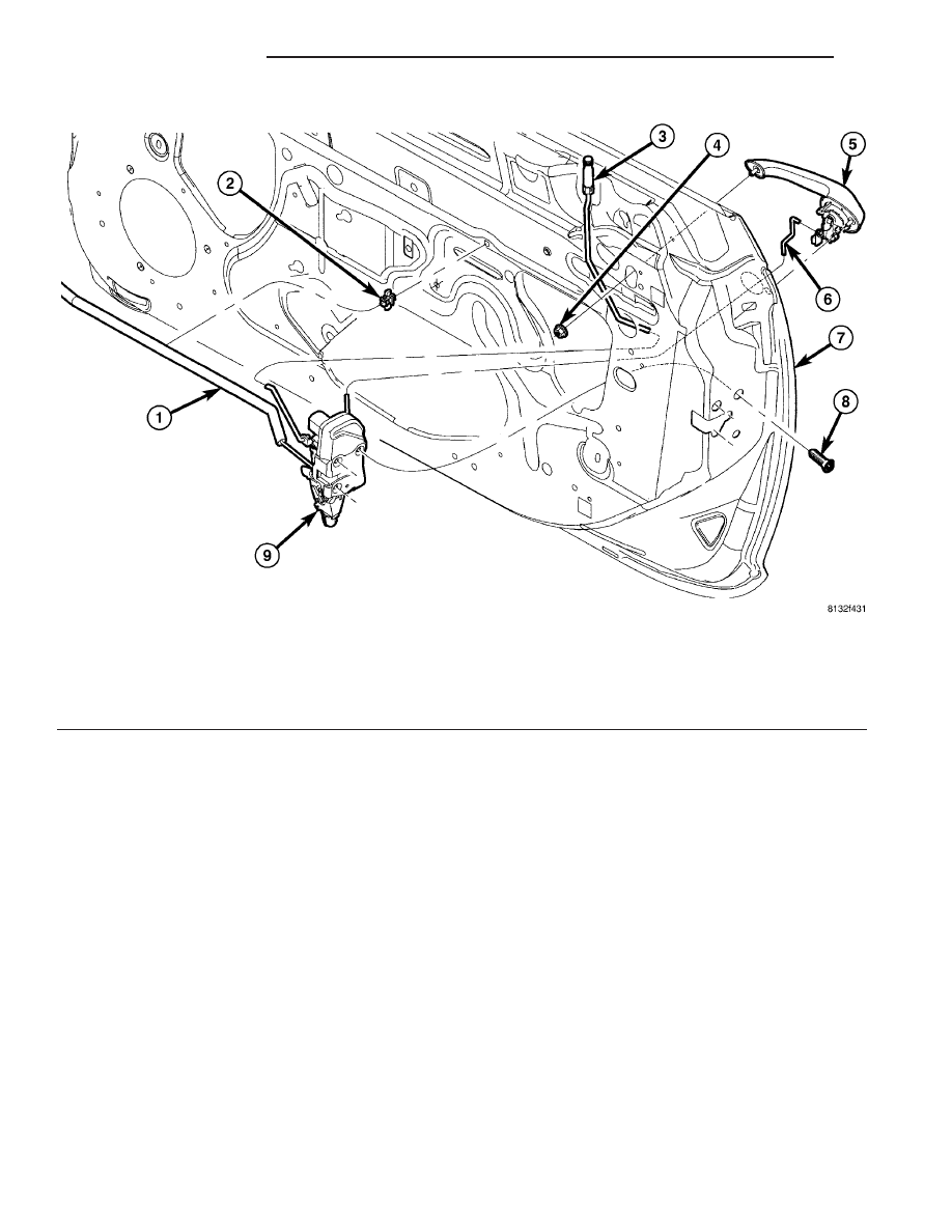
Fig. 27 DOOR HANDLE AND LATCH ASSEMBLY

1 - INSIDE REMOTE LINK AND SLEEVE
2 - LINK CLIP
3 - LOCKING KNOB AND ROD
4 - HANDLE NUT
5 - OUTSIDE HANDLE

6 - OUTSIDE HANDLE TO LATCH LINK
7 - FRONT DOOR
8 - LATCH ATTACHING SCREW(S)
9 - DOOR LATCH

23 - 62

DOOR - FRONT

PT

FRONT DOOR OUTSIDE HANDLE (Continued)

REMOVAL - PT-27 ONLY

(1) Open and support door on a suitable lifting

device.

(2) Remove bolts attaching door check strap to

lower A-pillar for greater access, if necessary (Fig.
28).

(3) Mark position of hinge on both the door end

frame and lower A-pillar to ease installation.

(4) Remove bolts attaching hinge to door end

frame.

(5) Remove bolts attaching hinge to lower A-pillar.
(6) Remove door hinge from vehicle.

INSTALLATION

INSTALLATION

CAUTION: When installing a new hinge, make sure
that the head of each hinge pin is fully seated into
the door hinge. Also, remove the plastic shipping
clip and replace it with the correct metal retaining
clip once the hinge pin is seated.

(1) If necessary, paint new door hinge prior to

installation.

(2) Position door hinge on vehicle (Fig. 4).
(3) Loosely install bolts attaching hinge to lower

A-pillar.

(4) Loosely install bolts attaching hinge to door

end frame.

(5) Align hinge to marks made previously and

tighten all bolts.

(6) Install bolts attaching door check strap to

lower A-pillar, if removed previously.

(7) Verify door fit and operation. Adjust door hinge

for proper door alignment, if necessary.

INSTALLATION - PT-27 ONLY

CAUTION: When installing a new hinge, make sure
that the head of each hinge pin is fully seated into
the door hinge. Also, remove the plastic shipping
clip and replace it with the correct metal retaining
clip once the hinge pin is seated.

(1) If necessary, paint new door hinge prior to

installation.

(2) Position door hinge on vehicle (Fig. 28).
(3) Loosely install bolts attaching hinge to lower

A-pillar.

(4) Loosely install bolts attaching hinge to door

end frame.

(5) Align hinge to marks made previously and

tighten all bolts.

(6) Install bolts attaching door check strap to

lower A-pillar, if removed previously.

(7) Verify door fit and operation. Adjust door hinge

for proper door alignment, if necessary.

FRONT DOOR INSIDE HANDLE
ACTUATOR

REMOVAL

(1) Remove the door trim panel.

CAUTION: Do not use a drill to remove the heat
stakes.

(2) Remove the heat stakes using a razor knife or

equivalent and remove the door handle. (Fig. 29)

(3) Remove the front door inside remote handle/

power door lock switch bezel.

INSTALLATION

NOTE: Clean the excess heat staking off of the
studs to aid installation.

(1) Install the new inside door handle, install the

screws and hand tighten. (Fig. 30)

(2) If necessary renew the upper heat stake. Refer

to page 23-28 for heat staking procedure. (Fig. 30)

Fig. 28 FRONT DOOR - PT-27

1 - FRONT DOOR UPPER HINGE
2 - FRONT DOOR CHECK STRAP
3 - FRONT DOOR
4 - FRONT DOOR LOWER HINGE

PT

DOOR - FRONT

23 - 63

FRONT DOOR HINGE (Continued)

(3) Install the remote handle/power door lock

switch bezel.

(4) Install the door trim panel.

FRONT DOOR LATCH

REMOVAL

REMOVAL

(1) Remove door trim panel and water shield.
(2) Raise door glass.
(3) Disconnect lock and latch rods from door latch

(Fig. 26)and (Fig. 31).

(4) Disengage wire connector from power door lock

motor, if equipped.

(5) Remove screws attaching latch to door end

frame.

(6) Remove door latch from vehicle.

Fig. 29 INSIDE HANDLE ACTUATOR

1 - INSIDE HANDLE ACTUATOR
2 - HEAT STAKES

Fig. 30 FRONT DOOR INSIDE HANDLE ACTUATOR

1 - HEAT STAKE LOCATION
2 - INSIDE HANDLE ACTUATOR
3 - PHILLIPS TYPE SCREWS

Fig. 31 FRONT DOOR LATCH

1 - FRONT DOOR OUTSIDE HANDLE TO LATCH LINK
2 - FRONT DOOR LOCK KNOB TO LATCH LINK
3 - FRONT DOOR KEY CYLINDER TO LATCH LINK
4 - FRONT DOOR OVERRIDE MANUAL LOCK LATCH
5 - FRONT DOOR OVERRIDE POWER LOCK LATCH
6 - FRONT DOOR OVERRIDE POWER LOCK LATCH
CONNECTION
7 - FRONT DOOR INSIDE REMOTE HANDLE LINK AND SLEEVE
TO LATCH

23 - 64

DOOR - FRONT

PT

FRONT DOOR INSIDE HANDLE ACTUATOR (Continued)

REMOVAL - PT-27 ONLY

(1) Remove door trim panel and water shield.
(2) Raise door glass.
(3) Disconnect lock and latch rods from door latch

(Fig. 32)and (Fig. 33).

(4) Disengage wire connector from power door lock

motor, if equipped.

(5) Remove screws attaching latch to door end

frame.

(6) Remove door latch from vehicle.

INSTALLATION

INSTALLATION

CAUTION: Do not close door before adjusting the
door latch. Door may fail to open.

(1) Position door latch inside door and install

screws holding latch to door end frame (Fig. 26) and
(Fig. 31).

(2) Engage wire connector into power door lock

motor, if so equipped.

(3) Connect latch and lock rods to door latch.
(4) Install door trim panel and water shield.
(5) Adjust door latch using procedure in this sec-

tion.

INSTALLATION - PT-27 ONLY

CAUTION: Do not close door before adjusting the
door latch. Door may fail to open.

(1) Position door latch inside door and install

screws attaching latch to door end frame (Fig. 32)and
(Fig. 33).

(2) Engage wire connector into power door lock

motor, if so equipped.

(3) Connect latch and lock rods to door latch.
(4) Install door trim panel and water shield.
(5) Adjust door latch using procedure in this sec-

tion.

ADJUSTMENTS

FRONT DOOR LATCH ADJUSTMENT

(1) Insert a Torx

t-wrench through the elongated

hole in the door end frame near the latch striker
opening.

(2) Loosen Torx

t head screw on the side of the

latch linkage.

(3) Push button on outside door handle and release

it.

(4) Tighten Torx

t head screw on latch.

(5) Verify latch operation.

ADJUSTMENT - PT-27 ONLY

(1) Insert a Torx

t wrench through the elongated

hole in the door end frame near the latch striker
opening.

(2) Loosen Torx

t head screw on the side of the

latch linkage.

(3) Push button on outside door handle and release

it.

(4) Tighten Torx

t head screw on latch.

(5) Verify latch operation.

Fig. 32 DOOR LATCH

Fig. 33 DOOR LATCH

1 - INSIDE REMOTE LINK AND SLEEVE
2 - DOOR LATCH LOCKING KNOB AND ROD
3 - DOOR OUTSIDE HANDLE TO LATCH
4 - DOOR KEY CYLINDER TO LATCH LINK
5 - DOOR WITH POWER LOCK, WITH DOOR AJAR LATCH
6 - WIRING CONNECTOR, DOOR LOCK

PT

DOOR - FRONT

23 - 65

FRONT DOOR LATCH (Continued)


Content   ..  899  900  901  902   ..