Chrysler PT Cruiser. Manual - part 892


  Index      Chrysler     Chrysler PT Cruiser - service repair manual 2005 year


Search            


Content   ..  890  891  892  893   ..


Chrysler PT Cruiser. Manual - part 892


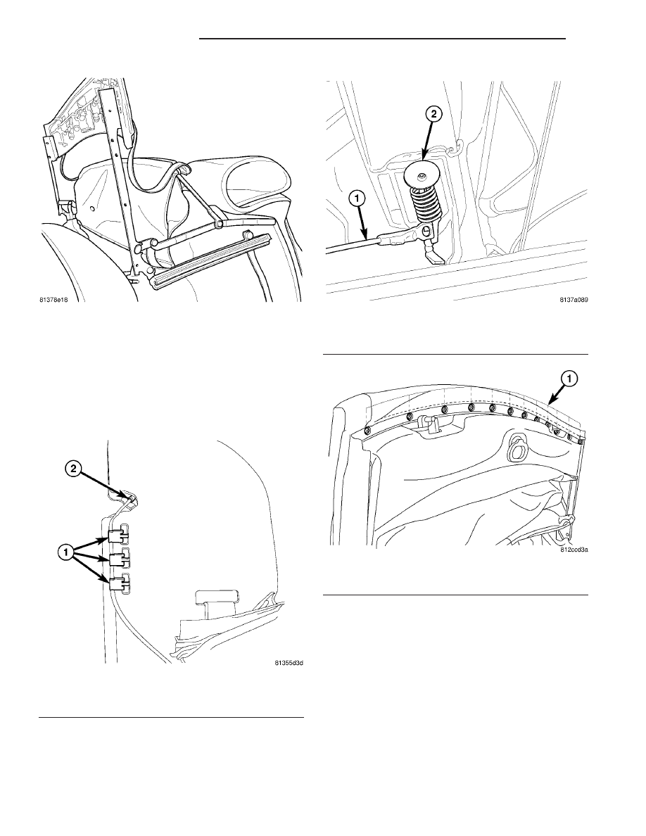
(15) Install tension cable with two spring clips on

each side (Fig. 44) and (Fig. 45).

(16) Install canopy adhesive tape to the front

header edges.

(17) Install 12 screws attaching Canopy to front

header (Fig. 46).

(18) Operate the folding top assembly to ensure

proper operation and fit.

Fig. 43 CANOPY FOLDED BACK

Fig. 44 CABLE

1 - THREE CLIPS
2 - CABLE END

Fig. 45 TENSION CABLE SPRING

1 - CABLE
2 - SPRING

Fig. 46 TOP COVER FRONT HEADER

1 - ATTACHING SCREWS (12)

23 - 26

CONVERTIBLE TOP

PT

FOLDING TOP COVER ASSEMBLY (Continued)

HEADLINER ASSEMBLY

REMOVAL

(1) Open the folding top to half open position that

each area is able to access (Fig. 47).

(2) Unscrew 12 screws to remove Canopy from

front header (Fig. 48).

(3) Remove canopy adhesive tape from the front

header edges.

(4) Remove tension cable with two spring clips on

each side (Fig. 49) and (Fig. 50).

(5) Fold the canopy back to the B-bow (Fig. 51)

and (Fig. 52).

(6) Unscrew nine screws to remove the headliner

from the front header.

Fig. 47 PARTIAL UP POSITION

Fig. 48 TOP COVER FRONT HEADER

1 - ATTACHING SCREWS (12)

Fig. 49 CABLE

1 - THREE CLIPS
2 - CABLE END

Fig. 50 TENSION CABLE SPRING

1 - CABLE
2 - SPRING

PT

CONVERTIBLE TOP

23 - 27

(7) Remove five screws from each bow strip (Fig.

53).

(8) Remove the headliner attachments (elastic

straps) from the folding top frame.

(9) Remove C-Post flaps from the C-Post stamping

(two expanding two rivets per side) (Fig. 54).

(10) Remove screws from the floating bow to

detach the headliner (Fig. 55).

(11) Remove the headliner extrusion profile from

the backlite frame (Fig. 56).

(12) Remove five screws from the edge bow strip

(Fig. 57).

(13) Remove the headliner.

Fig. 51 CANOPY AT B-BOW

Fig. 52 CANOPY FOLDED BACK

Fig. 53 D-BOW

1 - C-BOW
2 - D-BOW

Fig. 54 SEALS

1 - CONTOUR BOW 2 SEAL
2 - C-POST LINKAGE SEAL

23 - 28

CONVERTIBLE TOP

PT

HEADLINER ASSEMBLY (Continued)

INSTALLATION

(1) Place headliner into position.
(2) Install five screws into the edge bow strip (Fig.

58) and (Fig. 59).

(3) Install the headliner extrusion profile to the

backlite frame (Fig. 60).

(4) Install screws into the floating bow to attach

the headliner (Fig. 61).

Fig. 55 HEADLINER SCREW

1 - HEADER COVER
2 - HEADER ATTACHING SCREW

Fig. 56 WATER TROUGH

1 - WATER TROUGH

Fig. 57 E-BOW

1 - C-BOW
2 - D-BOW
3 - E-BOW (EDGE BOW)

PT

CONVERTIBLE TOP

23 - 29

HEADLINER ASSEMBLY (Continued)


Content   ..  890  891  892  893   ..