Chrysler PT Cruiser. Manual - part 756


  Index      Chrysler     Chrysler PT Cruiser - service repair manual 2005 year


Search            


Content   ..  754  755  756  757   ..


Chrysler PT Cruiser. Manual - part 756


(16) Remove remaining four screws fastening radi-

ator fan to cooling module (Fig. 16). Remove fan.

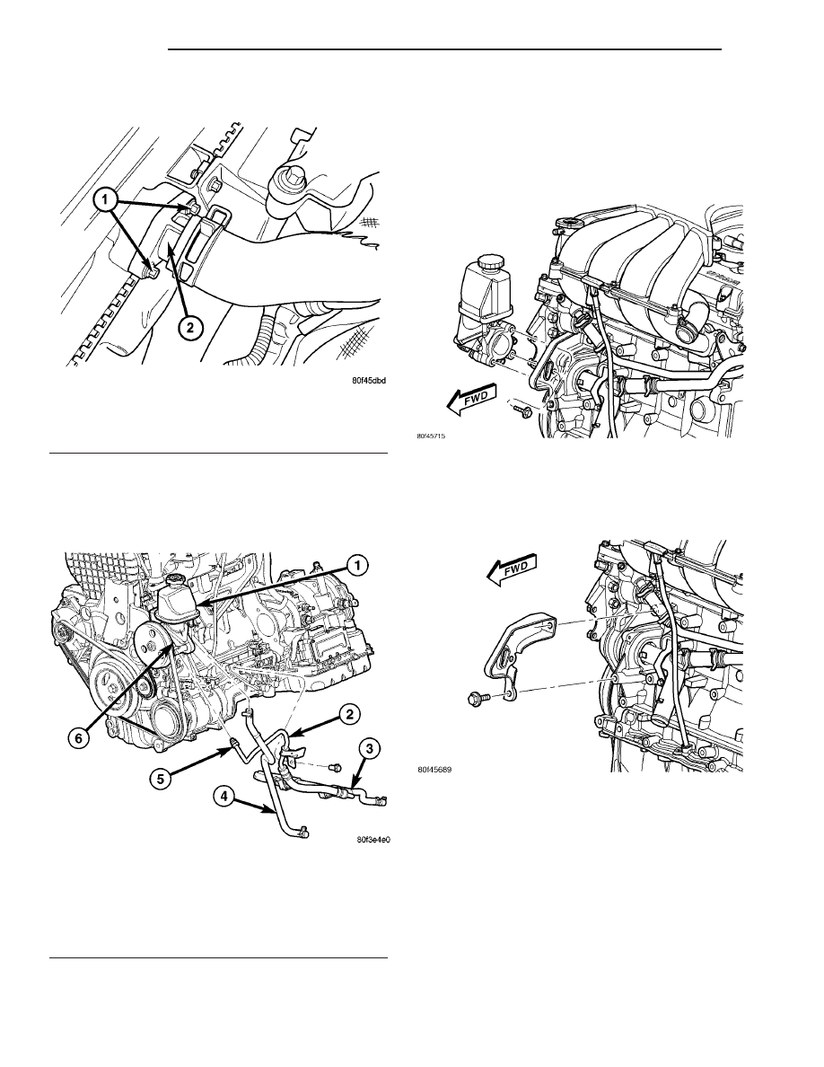
(17) Remove clamp securing fluid return hose to

pump reservoir (Fig. 19), then remove hose from res-
ervoir fitting. Cap off hose end and reservoir fitting.

(18) Back out tube nut securing fluid pressure

hose to power steering pump and remove hose from
pump (Fig. 19). Cap off hose end and pump pressure
port.

(19) Remove three mounting bolts securing power

steering pump in place (Fig. 20).

(20) Remove 2 bolts securing stamped steel sup-

port bracket to engine block (Fig. 21). Remove
bracket.

(21) Remove power steering pump with pulley and

reservoir attached.

REMOVAL - 2.2L DIESEL

The power steering pump is attached to the water

pump as an assembly on the engine. To remove the
power steering pump, (Refer to 7 - COOLING/EN-
GINE/WATER PUMP - REMOVAL).

Fig. 18 Radiator Inlet Neck - 2.4L Turbo

1 - FASTENERS
2 - RADIATOR INLET NECK

Fig. 19 Hoses At Pump And Engine - 2.4L Turbo

1 - RESERVOIR (MOUNTED TO PUMP)
2 - PRESSURE HOSE (SERVICED WITH RETURN HOSE)
3 - RETURN HOSE (SERVICED WITH PRESSURE HOSE)
4 - RETURN HOSE (COOLING MODULE TO RESERVOIR)
5 - TUBE NUT
6 - POWER STEERING PUMP

Fig. 20 Pump Mounting - 2.4L Turbo

Fig. 21 Bracket Mounting To Engine - 2.4L Turbo

19 - 42

PUMP

PT

PUMP (Continued)

DISASSEMBLY

NOTE: The only serviceable part of the power steer-
ing pump is the pulley. The following procedure is
for the removal and installation of the pulley from
the pump.

NOTE: The power steering pump must be removed
from the vehicle for power steering pump pulley
service. (Refer to 19 - STEERING/PUMP - REMOVAL)

CAUTION: Use care when removing and installing
the power steering pump pulley. It is made of plas-
tic composite, except for the center shank. Use the
special tools in the shank area only as described in
the following procedure.

CAUTION: Do not hammer on the power steering
pump pulley or shaft to remove the power steering
pump pulley. This will damage the pulley and the
power steering pump.

(1) Install Puller, Special Tool C-4333, or an equiv-

alent, on the steering pump pulley as shown (Fig.
22). Tighten the puller screw drive and remove the
pulley from the power steering pump shaft.

(2) Remove the puller from the pulley.

ASSEMBLY

CAUTION: Use care when removing and installing
the power steering pump pulley. It is made of plas-
tic composite, except for the center shank. Use the
special tools in the shank area only as described in
the following procedure.

NOTE: Replace the power steering pump pulley if it
is cracked or loose.

(1) Place the power steering pump pulley squarely

on end of the power steering pump shaft. Mount
Installer, Special Tool C-4063, or an equivalent, in
the internal threads of the power steering pump
shaft and against power steering pump pulley (Fig.
23).

(2) Ensuring that the installer and the pulley

remain aligned with the pump shaft, turn the
installer outer nut and force the pulley onto the
power steering pump shaft until it is flush with the
end of the pump shaft. Once the pulley is flush with
the end of the shaft, the installer outer nut will no
longer be able to turn.

(3) Remove the installer from the power steering

pump.

(4) Install the power steering pump back on the

engine. (Refer to 19 - STEERING/PUMP - INSTAL-
LATION)

INSTALLATION

INSTALLATION - 1.6L ENGINE

The power steering pump is attached to the water

pump as an assembly on the engine. To install the
power steering pump, (Refer to 7 - COOLING/EN-
GINE/WATER PUMP - INSTALLATION).

INSTALLATION - 2.0L/2.4L ENGINE

(1) Using a lint free towel, wipe clean the open

power steering pressure hose end and the power
steering pump port. Replace any used O-rings with
new. Lubricate the O-ring with clean power steering
fluid.

Fig. 22 Pulley Removal

Fig. 23 Pulley Installation

PT

PUMP

19 - 43

PUMP (Continued)

(2) Ease the cooling module forward, don’t force it,

and install the power steering pump and pulley into
its mounting area in the same fashion it was
removed (Fig. 14).

(3) Place the pump in mounting position with the

stamped steel support bracket behind it (Fig. 13).
Install the three bolts through the bracket and
pump, into the threaded engine cover. Do not tighten
the bolts at this time.

(4) Install the two bolts fastening the bracket to

the engine block (Fig. 13). Tighten the two bolts to a
torque of 54 N·m (40 ft. lbs.).

(5) Tighten the three pump mounting bolts previ-

ously installed to a torque of 28 N·m (250 in. lbs.).

(6) Push the fluid supply hose onto the pump sup-

ply fitting. Expand the hose clamp and slide it over
the hose and pump supply fitting (Fig. 12). Secure
the clamp once it is past the bead formed into the
fluid reservoir fitting.

CAUTION: Make sure the supply hose is routed
above the engine timing chain cover. The power
steering fluid supply hose must remain clear of any
unfriendly surface that can cause possible damage
to it.

(7) Raise the vehicle.
(8) Thread the fluid pressure hose tube nut into

the pump (Fig. 6) (Fig. 7).

(9) Using a crowfoot wrench on a long extension

with a torque wrench, tighten the pressure hose tube
nut at the power steering pump to a torque of 31
N·m (23 ft. lbs.).

(10) Install the four bolts fastening the A/C com-

pressor to the engine (Fig. 5). Tighten the mounting
bolts to a torque of 28 N·m (250 in. lbs.).

(11) Install the A/C compressor electrical connec-

tors (Fig. 5).

(12) Install the A/C drive belt. Refer to the Cooling

section for the procedure.

(13) Install the drive-belt splash shield and fasten-

ers (Fig. 4).

(14) Install the screws fastening the front fascia to

the reinforcement (Fig. 4).

(15) Install the right front tire and wheel assem-

bly. Install and tighten the wheel mounting nuts to a
torque of 135 N·m (100 ft. lbs.).

(16) Lower the vehicle.
(17) Remove the bungee cord and move the cooling

module back into is lower mounts.

(18) If previously removed, install the right side

bolts securing the lower radiator closure panel in
front of the cooling module.

(19) Install the radiator closure panel and fasten it

in place (Fig. 10).

(20) Install the ambient temperature sensor on the

radiator closure panel (Fig. 9).

(21) Install the hood-opening weather-strip across

the radiator closure panel.

(22) Install the grille on the front of the vehicle

(Fig. 8).

(23) Perform the POWER STEERING PUMP INI-

TIAL OPERATION service procedure to properly fill
and bleed the power steering system. (Refer to 19 -
STEERING/PUMP - STANDARD PROCEDURE)

(24) Check for leaks.

INSTALLATION - 2.4L TURBO

(1) Using a lint free towel, wipe clean open power

steering pressure hose end and power steering pump
pressure port. Replace any used O-rings with new.
Lubricate O-ring with clean power steering fluid.

(2) Install power steering pump with pulley and

reservoir into its mounting area in same fashion it
was removed.

(3) Place pump in mounting position with stamped

steel support bracket behind it. Install three pump
mounting bolts through bracket and pump, into
threaded engine cover (Fig. 20). DO NOT TIGHTEN
BOLTS AT THIS TIME.

(4) Install two bolts fastening support bracket to

engine block (Fig. 21). Tighten two bolts to 54 N·m
(40 ft. lbs.) torque.

(5) Tighten three pump mounting bolts previously

installed (Fig. 20) to 28 N·m (250 in. lbs.) torque.

(6) Thread pressure hose tube nut into pump pres-

sure fitting (Fig. 19). Tighten tube nut to 31 N·m (23
ft. lbs.) torque.

(7) Install fluid return hose onto power steering

fluid reservoir return fitting (Fig. 19). Expand hose
clamp and slide it over hose and pump return fitting.
Secure clamp once it is past bead formed into fluid
reservoir fitting.

(8) Position radiator fan and install two upper and

two side mounting screws (Fig. 16). DO NOT
TIGHTEN SCREWS AT THIS TIME.Tighten screws
to 6 N·m (55 in. lbs.) torque.

(9) Position cooling module back into its lower

mounts.

(10) Clean and inspect or replace upper radiator

hose inlet neck O-ring, then install inlet neck to radi-
ator (Fig. 18). Install 2 mounting screws.

(11) Install radiator closure panel and fasten it in

place (Fig. 10).

(12) Install ambient temperature sensors on radia-

tor closure panel (Fig. 17).

(13) Install

hood-opening

weather-strip

across

radiator closure panel.

(14) Install grille on front of vehicle (Fig. 8).
(15) Raise vehicle.
(16) Install accessory drive belt. (Refer to 7 -

COOLING/ACCESSORY

DRIVE/DRIVE

BELTS

-

INSTALLATION)

19 - 44

PUMP

PT

PUMP (Continued)

(17) Install accessory drive belt splash shield.
(18) Install two remaining lower fan mounting

screws (Fig. 16). Tighten screws to 6 N·m (55 in. lbs.)
torque.

(19) Connect radiator fan wiring connector (Fig.

15).

(20) Install right front tire and wheel assembly.

Install and tighten wheel mounting nuts to 135 N·m
(100 ft. lbs.) torque.

(21) Lower vehicle.
(22) Tighten two upper and two side radiator fan

mounting screws to 6 N·m (55 in. lbs.) torque (Fig.
16).

(23) Fill cooling system (Refer to 7 - COOLING -

STANDARD PROCEDURE - FILLING COOLING
SYSTEM).

(24) Perform POWER STEERING PUMP INITIAL

OPERATION procedure to properly fill and bleed
power steering system. (Refer to 19 - STEERING/
PUMP - STANDARD PROCEDURE)

(25) Check for leaks.

INSTALLATION - 2.2L DIESEL

The power steering pump is attached to the water

pump as an assembly on the engine. To install the
power steering pump, (Refer to 7 - COOLING/EN-
GINE/WATER PUMP - INSTALLATION).

FLUID

STANDARD PROCEDURE - POWER STEERING
FLUID LEVEL CHECKING

WARNING: FLUID LEVEL SHOULD BE CHECKED
WITH THE ENGINE OFF TO PREVENT PERSONAL
INJURY FROM MOVING PARTS.

CAUTION: Use only Mopar

T

ATF+4 Automatic Trans-

mission Fluid (MS-9602) in the power steering sys-
tem. Do not overfill.

1.6L GAS/2.2L DIESEL ENGINE

The power steering fluid level can be viewed

through the side of the power steering fluid reservoir.
Compare the fluid level to the markings on the side
of the reservoir. When the fluid is at normal ambient
temperature, approximately 21°C to 27°C (70°F to
80°F), the fluid level should read between the MAX.
COLD and MIN. COLD markings. When the fluid is
hot, fluid level is allowed to read up to the highest
end of the MAX. HOT range.

2.0L/2.4L ENGINE

The power steering fluid level can be viewed on the

dipstick attached to the filler cap. There are two
ranges listed on the dipstick, COLD and HOT. Before
opening power steering system, wipe the reservoir
filler cap free of dirt and debris. Remove the cap and
check the fluid level on the dipstick. When the fluid
is at normal ambient temperature, approximately
21°C to 27°C (70°F to 80°F), the fluid level should
read between the minimum and maximum area of
the COLD range. When the fluid is hot, fluid level is
allowed to read up to the highest end of the HOT
range.

2.4L TURBO ENGINE

The power steering fluid level can be viewed on the

dipstick attached to the filler cap. Before opening
power steering system, wipe the reservoir filler cap
free of dirt and debris. Remove the cap and check the
fluid level on the dipstick. When the fluid is at nor-
mal ambient temperature, approximately 21°C to
27°C (70°F to 80°F), the fluid level should read
between the FULL and ADD markings.

FLUID COOLER

DESCRIPTION

All models of this vehicle are equipped with a

cooler for the power steering system fluid. Vehicles
not equipped with a turbocharged engine use a power
steering fluid cooler that is located at the front of the
front suspension crossmember (Fig. 24) (Fig. 25). It is
mounted to the crossmember top surface using 2 fas-
teners. Vehicles equipped with a turbocharged engine
use a cooler that is integrated into the radiator.

The cooler is placed in series with the power steer-

ing fluid return hose, between the steering gear fluid
outlet port and the fluid return hose leading to the
power steering fluid reservoir.

REMOVAL - NON-TURBO ENGINES

NOTE: Before proceeding, (Refer to 19 - STEERING
- WARNING).

(1) Siphon as much fluid as possible from the

power steering fluid reservoir.

(2) Raise the vehicle. (Refer to LUBRICATION &

MAINTENANCE/HOISTING - STANDARD PROCE-
DURE).

(3) Remove the hose clamp attaching the power

steering fluid return hose to the power steering fluid
cooler. Remove the return hose from the cooler.

PT

PUMP

19 - 45

PUMP (Continued)


Content   ..  754  755  756  757   ..