Chrysler PT Cruiser. Manual - part 755


  Index      Chrysler     Chrysler PT Cruiser - service repair manual 2005 year


Search            


Content   ..  753  754  755  756   ..


Chrysler PT Cruiser. Manual - part 755


CAUTION: Use only Mopar

T

ATF+4 Automatic Trans-

mission Fluid (MS-9602) in the power steering sys-
tem. Do not overfill.

(1) Fill the power steering fluid reservoir to the

proper level, then let the fluid settle for at least two
minutes. (Refer to 19 - STEERING/PUMP/FLUID -
STANDARD PROCEDURE - POWER STEERING
FLUID LEVEL CHECKING)

(2) Start the engine and let run for a few seconds,

then turn the engine off.

(3) Add fluid if necessary. Repeat the above proce-

dure until the fluid level remains constant after run-
ning the engine.

(4) Raise the front wheels off the ground.
(5) Start the engine. Slowly turn the steering

wheel right and left, lightly contacting the wheel
stops.

(6) Add power steering fluid if necessary.
(7) Lower the vehicle and turn the steering wheel

slowly from lock to lock.

(8) Stop the engine. Check the fluid level and refill

as required.

(9) If the fluid is extremely foamy, allow the vehi-

cle to stand a few minutes and repeat the above pro-
cedure.

REMOVAL

REMOVAL - 1.6L ENGINE

The power steering pump is attached to the water

pump as an assembly on the engine. To remove the
power steering pump, (Refer to 7 - COOLING/EN-
GINE/WATER PUMP - REMOVAL).

REMOVAL - 2.0L/2.4L ENGINE

NOTE: Before proceeding, (Refer to 19 - STEERING
- WARNING).

(1) Siphon as much fluid as possible from the

power steering fluid reservoir.

(2) Raise the vehicle. (Refer to LUBRICATION &

MAINTENANCE/HOISTING - STANDARD PROCE-
DURE)

(3) Remove the right front tire and wheel assem-

bly.

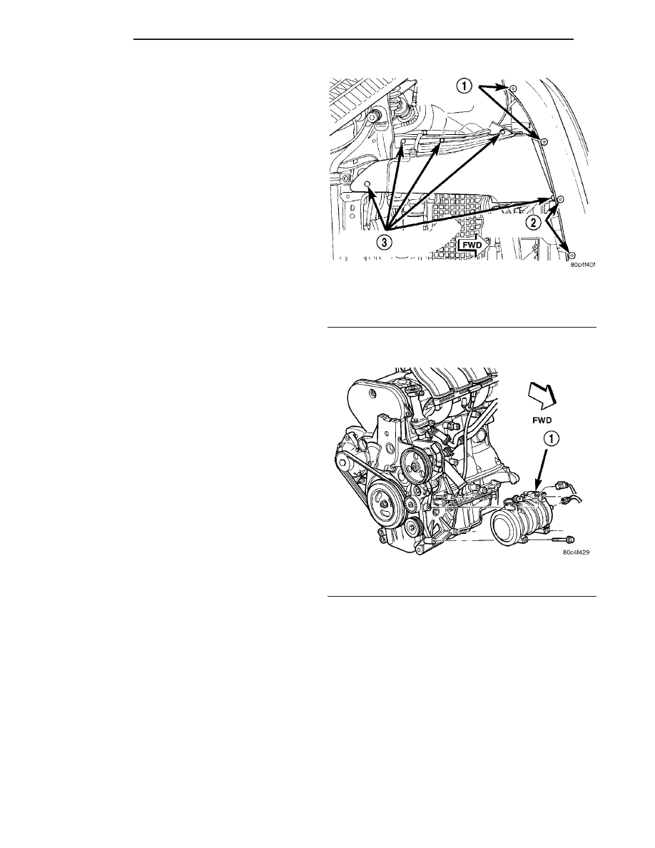
(4) Remove the screws fastening the front fascia to

the reinforcement as necessary in order to access the
drive-belt splash shield forward fastener screw (Fig.
4).

(5) Remove the drive-belt splash shield fasteners

(Fig. 4). Remove the shield.

(6) Remove the accessory drive-belt from the A/C

compressor and power steering pump. Refer to the
Cooling section for the procedure.

(7) Remove the electrical connectors from the A/C

compressor (Fig. 5).

(8) Remove the four bolts fastening the A/C com-

pressor to the engine (Fig. 5), then move the com-
pressor toward the center of the vehicle, allowing the
compressor to settle in place.

(9) Remove the pressure hose from the pump in

the following fashion (Fig. 6) (Fig. 7):

(a) Place a crowfoot wrench on a long extension

onto the pressure hose tube nut at the pump.

(b) Place a shop towel between the crowfoot and

the pump pulley to avoid slipping and possibly
damaging the pulley.

(c) Unthread the tube nut from the pump.

(10) Lower the vehicle.
(11) Remove the grille from the front of the vehicle

(Fig. 8).

Fig. 4 Fascia And Splash Shield Fasteners

1 - FASCIA FASTENERS
2 - FASCIA FASTENERS
3 - SPLASH SHIELD FASTENERS

Fig. 5 A/C Compressor Mounting

1 - COMPRESSOR

19 - 38

PUMP

PT

PUMP (Continued)

(12) Remove the hood-opening weather-strip from

across the radiator closure panel.

(13) Remove the ambient temperature sensor from

the radiator closure panel (Fig. 9).

(14) Remove the fasteners securing the upper radi-

ator closure panel in place (Fig. 10), then remove the
panel.

(15) Lift the cooling module out of its lower

mounts and carefully move it toward the left side of
the vehicle. It will move only a limited amount with
the hoses still connected. Do not force it.

NOTE: For additional room, the right side bolts
securing the lower radiator closure panel in front of
the cooling module can be removed.

(16) Using a bungee cord, tie the cooling module

forward as shown (Fig. 11). Be sure to attach the
cord in a location that will not damage the vehicle.
Do not overtighten the bungee cord. It just needs to
hold the module forward.

(17) Remove the clamp securing the supply hose to

the power steering pump supply fitting (Fig. 12),
then remove the hose from the supply fitting.

Fig. 6 Pressure Hose Connection To Pump

1 - PUMP
2 - PRESSURE HOSE

Fig. 7 Pressure Hose Tube Nut

1 - PUMP PULLEY
2 - POWER STEERING PUMP
3 - PRESSURE HOSE TUBE NUT

Fig. 8 Grille Attachment

1 - GRILLE
2 - RETAINER

Fig. 9 Ambient Temperature Sensor

1 - FASTENER
2 - SENSOR

PT

PUMP

19 - 39

PUMP (Continued)

(18) Remove the three bolts securing the pump in

place (Fig. 13).

(19) Remove the 2 bolts securing the stamped steel

support bracket to the engine block (Fig. 13). Remove
the bracket.

(20) Ease the cooling module forward, don’t force

it, and remove the power steering pump and pulley
where shown (Fig. 14).

Fig. 10 Radiator Closure Panel

1 - FASTENERS

Fig. 11 Cooling Module Tied Forward

1 - COOLING MODULE

Fig. 12 Supply Hose At Pump

1 - SUPPLY HOSE CLAMP
2 - POWER STEERING PUMP

Fig. 13 Mounting Bolts

1 - POWER STEERING PUMP
2 - SUPPORT

Fig. 14 Power Steering Pump Removal

19 - 40

PUMP

PT

PUMP (Continued)

REMOVAL - 2.4L TURBO

NOTE: Before proceeding, (Refer to 19 - STEERING
- WARNING).

(1) Siphon as much fluid as possible from power

steering fluid reservoir.

(2) Raise vehicle. (Refer to LUBRICATION &

MAINTENANCE/HOISTING - STANDARD PROCE-
DURE)

(3) Drain engine coolant (Refer to 7 - COOLING/

ENGINE - STANDARD PROCEDURE - DRAIN
COOLING SYSTEM).

(4) Remove right front tire and wheel assembly.
(5) Disconnect radiator fan wiring connector (Fig.

15).

(6) Remove two lower fan mounting screws (Fig.

16).

(7) Remove accessory drive belt splash shield.
(8) Remove accessory drive belt. (Refer to 7 -

COOLING/ACCESSORY

DRIVE/DRIVE

BELT

-

REMOVAL)

(9) Lower vehicle.
(10) Remove grille from front of vehicle (Fig. 8).
(11) Remove

hood-opening

weather-strip

from

across radiator closure panel.

(12) Remove ambient temperature sensors from

radiator closure panel (Fig. 17).

(13) Remove fasteners securing upper radiator clo-

sure panel in place (Fig. 10), then remove the panel
and lay it out of way.

(14) Remove 2 screws fastening upper radiator

hose inlet neck to radiator, then separate inlet neck
from radiator (Fig. 18).

(15) Carefully tip top of cooling module toward

front of vehicle. DO NOT FORCE IT. Using a bungee
cord or equivalent, tie the module forward in this
position. Be sure to attach the cord in a location that
will not damage the vehicle. Do not overtighten the
bungee cord. It just needs to hold the module for-
ward.

Fig. 15 Radiator Fan Connector - 2.4L Turbo

1 - RADIATOR FAN CONNECTOR
2 - RADIATOR DRAINCOCK

Fig. 16 Fan Mounting To Cooling Module - 2.4L

Turbo

1 - RADIATOR FAN FASTENERS
2 - CHARGE AIR COOLER FASTENERS
3 - RADIATOR FAN CONNECTOR
4 - CHARGE AIR COOLER

Fig. 17 Temperature Sensor Mounting

1 - AMBIENT TEMP SENSOR
2 - AMBIENT TEMP SENSOR

PT

PUMP

19 - 41

PUMP (Continued)


Content   ..  753  754  755  756   ..