Chrysler PT Cruiser. Manual - part 752


  Index      Chrysler     Chrysler PT Cruiser - service repair manual 2005 year


Search            


Content   ..  750  751  752  753   ..


Chrysler PT Cruiser. Manual - part 752


(6) Thread the wheel retaining bolt back into the

end of the shaft until approximately 13 mm (0.5 in.)
of thread is showing between the wheel and the head
of the bolt.

(7) Install a steering wheel puller on the steering

wheel.

CAUTION: Do not bump or hammer on steering
wheel or steering column shaft when removing
steering wheel from steering column.

(8) While holding the steering wheel firmly in the

STRAIGHT-AHEAD position, remove steering wheel
from the steering column shaft using the puller.

(9) Remove the wheel retaining bolt and the steer-

ing wheel. Take care to feed the wires gently through
the holes in the steering wheel.

INSTALLATION

(1) Confirm that:

(a) The front wheels are in the STRAIGHT-

AHEAD position.

(b) The turn signal stalk is in the neutral posi-

tion.
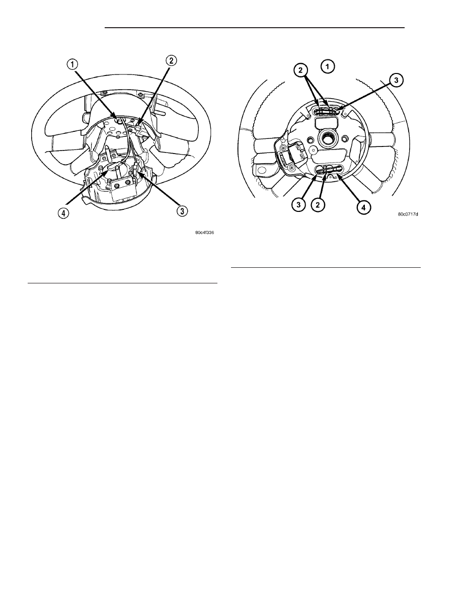
(2) Ensure the three foam rubber driver airbag

retaining clip pads are still in place on the rear of
the steering wheel (Fig. 40). Replace any missing
pads.

CAUTION: Do not install the steering wheel onto the
shaft of the steering column by driving it onto the
shaft.

(3) Feed the clockspring wiring leads through the

hole in the steering wheel. Align the steering wheel’s
wide mounting spline with the steering column shaft
missing spline area and push the wheel onto the
shaft. Make sure the clockspring lines up with the
back of the wheel and does not bind.

(4) Install the steering wheel retaining bolt and

tighten it until the steering wheel is fully installed
on shaft. Tighten the steering wheel retaining bolt to
54 N·m (40 ft. lbs.) torque.

(5) Install the driver airbag. (Refer to 8 - ELEC-

TRICAL/RESTRAINTS/DRIVER AIRBAG - INSTAL-
LATION)

WARNING: DO NOT CONNECT BATTERY NEGATIVE
CABLE YET. REFER FIRST TO AIRBAG SYSTEM
TEST. (Refer to 8 - ELECTRICAL/RESTRAINTS -
DIAGNOSIS AND TESTING)

(6) Reconnect battery using Airbag System Test

procedure in Restraints. (Refer to 8 - ELECTRICAL/
RESTRAINTS - DIAGNOSIS AND TESTING)

(7) Close hood.
(8) Verify vehicle and system operation.

Fig. 39 Steering Wheel Retaining Bolt

1 - STEERING WHEEL RETAINING BOLT
2 - SPEED CONTROL SWITCH CONNECTOR
3 - HORN SWITCH CONNECTOR
4 - AIRBAG CONNECTOR

Fig. 40 Foam Rubber Pad Locations

1 - TOP REAR OF STEERING WHEEL
2 - FOAM RUBBER PADS
3 - DRIVER AIRBAG RETAINING CLIP
4 - HORN GROUND AREA- NO PAD HERE

19 - 26

COLUMN

PT

STEERING WHEEL (Continued)

GEAR

TABLE OF CONTENTS

page

page

GEAR

DESCRIPTION

. . . . . . . . . . . . . . . . . . . . . . . . . 27

OPERATION

. . . . . . . . . . . . . . . . . . . . . . . . . . . 27

REMOVAL

REMOVAL

. . . . . . . . . . . . . . . . . . . . . . . . . . . 28

REMOVAL - RHD

. . . . . . . . . . . . . . . . . . . . . . 31

INSTALLATION

INSTALLATION

. . . . . . . . . . . . . . . . . . . . . . . 31

INSTALLATION - RHD

. . . . . . . . . . . . . . . . . . 33

POWER STEERING PRESSURE SWITCH

DESCRIPTION

. . . . . . . . . . . . . . . . . . . . . . . . . 33

OPERATION

. . . . . . . . . . . . . . . . . . . . . . . . . . . 33

REMOVAL

. . . . . . . . . . . . . . . . . . . . . . . . . . . . . 33

INSTALLATION

. . . . . . . . . . . . . . . . . . . . . . . . . 34

TIE ROD - OUTER

REMOVAL

. . . . . . . . . . . . . . . . . . . . . . . . . . . . . 34

INSTALLATION

. . . . . . . . . . . . . . . . . . . . . . . . . 35

GEAR

DESCRIPTION

The power steering gear is the rack-and-pinion

type. It is mounted on the front suspension cross-
member (Fig. 1). The outer ends of the outer tie rods
attach to the steering knuckles.

NOTE: The power steering gear should not be ser-
viced or adjusted. If a malfunction or oil leak occurs

with the steering gear, the complete steering gear
needs to be replaced.

OPERATION

Turning of the steering wheel is converted into lin-

ear (side-to-side) travel through the meshing of the
helical pinion teeth with the rack teeth in the steer-
ing gear. This travel pushes and pulls the tie rods to
change the direction of the vehicle’s front wheels.

Fig. 1 Power Steering Gear - LHD Shown

1 - OUTER TIE ROD
2 - JAM NUT

3 - STEERING GEAR
4 - FRONT SUSPENSION CROSSMEMBER

PT

GEAR

19 - 27

Power assist steering provided by the power steer-

ing pump is controlled by an open-center, rotary type
control valve which directs fluid from the pump to
either side of the integral rack piston upon demand.

Road feel is controlled by the diameter of a torsion

bar which initially steers the vehicle. As required
steering effort increases, as in a turn, the torsion bar
twists, causing relative rotary motion between the
rotary valve body and the valve spool. This move-
ment directs oil behind the integral rack piston
which, in turn, builds up hydraulic pressure and
assists in the turning effort.

Manual steering control of the vehicle can be main-

tained if power steering assist is lost. However,
under this condition, steering effort is significantly
increased.

REMOVAL

REMOVAL

NOTE: Before proceeding, (Refer to 19 - STEERING
- WARNING).

(1) Place the steering wheel in the STRAIGHT-

AHEAD position. Using a steering wheel holder, lock
the steering wheel in place to keep it from rotating
(Fig. 2). This keeps the clockspring in the proper ori-
entation.

(2) Remove the silencer pad below the knee

blocker panel below the steering column.

(3) Fold down and remove the knee blocker.
(4) Remove the steering column coupling retainer

pin, back off the pinch bolt nut, and remove the
steering column coupling pinch bolt (Fig. 3) (the
pinch bolt nut is caged to the coupling and is not
removable). Separate the upper and lower steering
column couplings.

(5) Raise the vehicle. (Refer to LUBRICATION &

MAINTENANCE/HOISTING - STANDARD PROCE-
DURE)

(6) Remove both front tire and wheel assemblies

from the vehicle.

(7) Remove nuts attaching both outer tie rods to

the steering knuckles (Fig. 4). Remove each nut by
holding the tie rod stud stationary while loosening
and removing the nut with a crowfoot wrench (or
open-end wrench).

(8) Remove the outer tie rods from the steering

knuckles using Remover, Special Tool MB991113
(Fig. 5).

(9) Remove the tie rod heat shields.

Fig. 2 Steering Wheel Holder

Fig. 3 Steering Column Couplings

1 - RETAINING PIN
2 - PINCH BOLT
3 - NUT

Fig. 4 Tools On Outer Tie Rod Nut

1 - OUTER TIE ROD
2 - STUD
3 - NUT

19 - 28

GEAR

PT

GEAR (Continued)

(10) On vehicles equipped with a power steering

fluid pressure switch, release the locking tab on the
wiring harness connector for the power steering fluid
pressure switch, then remove the wiring harness con-
nector from the power steering fluid pressure switch
(Fig. 6).

(11) Back out the tube nut securing the power

steering fluid pressure hose to the gear (Fig. 7) (Fig.
8).

(12) Disconnect the cooler or return hose at the

power steering gear outlet port fitting (Fig. 7) (Fig.
8).

(13) On

vehicles

equipped

with

crossmember

mounted power steering fluid coolers:

(a) Remove the cooler tube from the right rout-

ing clip.

(b) Remove the two screws securing the cooler to

the front suspension crossmember (Fig. 7). Allow
the cooler to hang out of the way.

Fig. 5 Tie Rod Removal From Knuckle

1 - OUTER TIE ROD
2 - STEERING KNUCKLE

Fig. 6 Power Steering Fluid Pressure Switch

1 - WIRING HARNESS CONNECTOR
2 - POWER STEERING GEAR
3 - POWER STEERING FLUID PRESSURE SWITCH
4 - REAR OF FRONT SUSPENSION CROSSMEMBER

Fig. 7 Cooler And Fluid Hose Mounting

1 - CROSSMEMBER
2 - COOLER
3 - RETURN HOSE
4 - PRESSURE HOSE

Fig. 8 Hoses At Power Steering Gear - 2.4L Turbo

1 - POWER STEERING GEAR
2 - ROUTING CLIP
3 - PRESSURE HOSE TUBE NUT
4 - RETURN HOSE CLAMP
5 - PRESSURE/RETURN HOSE ASSEMBLY

PT

GEAR

19 - 29

GEAR (Continued)


Content   ..  750  751  752  753   ..