Chrysler PT Cruiser. Manual - part 748


  Index      Chrysler     Chrysler PT Cruiser - service repair manual 2005 year


Search            


Content   ..  746  747  748  749   ..


Chrysler PT Cruiser. Manual - part 748


COLUMN

TABLE OF CONTENTS

page

page

COLUMN

DESCRIPTION

. . . . . . . . . . . . . . . . . . . . . . . . . 10

OPERATION

. . . . . . . . . . . . . . . . . . . . . . . . . . . 10

WARNING

WARNINGS AND CAUTIONS

. . . . . . . . . . . . . 11

DIAGNOSIS AND TESTING - STEERING

COLUMN

. . . . . . . . . . . . . . . . . . . . . . . . . . . . 11

REMOVAL

REMOVAL

. . . . . . . . . . . . . . . . . . . . . . . . . . . 11

REMOVAL - RHD

. . . . . . . . . . . . . . . . . . . . . . 15

INSTALLATION

INSTALLATION

. . . . . . . . . . . . . . . . . . . . . . . 16

INSTALLATION - RHD

. . . . . . . . . . . . . . . . . . 18

SPECIFICATIONS - STEERING COLUMN

FASTENER TORQUE

. . . . . . . . . . . . . . . . . . . 18

IGNITION SWITCH

REMOVAL

. . . . . . . . . . . . . . . . . . . . . . . . . . . . . 18

INSTALLATION

. . . . . . . . . . . . . . . . . . . . . . . . . 19

KEY/LOCK CYLINDER

REMOVAL

. . . . . . . . . . . . . . . . . . . . . . . . . . . . . 20

INSTALLATION

. . . . . . . . . . . . . . . . . . . . . . . . . 20

SHROUD - UPPER/LOWER

REMOVAL

. . . . . . . . . . . . . . . . . . . . . . . . . . . . . 21

INSTALLATION

. . . . . . . . . . . . . . . . . . . . . . . . . 21

STEERING COUPLING - LOWER

DESCRIPTION

. . . . . . . . . . . . . . . . . . . . . . . . . 21

OPERATION

. . . . . . . . . . . . . . . . . . . . . . . . . . . 21

DIAGNOSIS AND TESTING - STEERING

COLUMN LOWER COUPLING

. . . . . . . . . . . . 21

REMOVAL

. . . . . . . . . . . . . . . . . . . . . . . . . . . . . 22

INSTALLATION

. . . . . . . . . . . . . . . . . . . . . . . . . 24

STEERING WHEEL

REMOVAL

. . . . . . . . . . . . . . . . . . . . . . . . . . . . . 25

INSTALLATION

. . . . . . . . . . . . . . . . . . . . . . . . . 26

COLUMN

DESCRIPTION

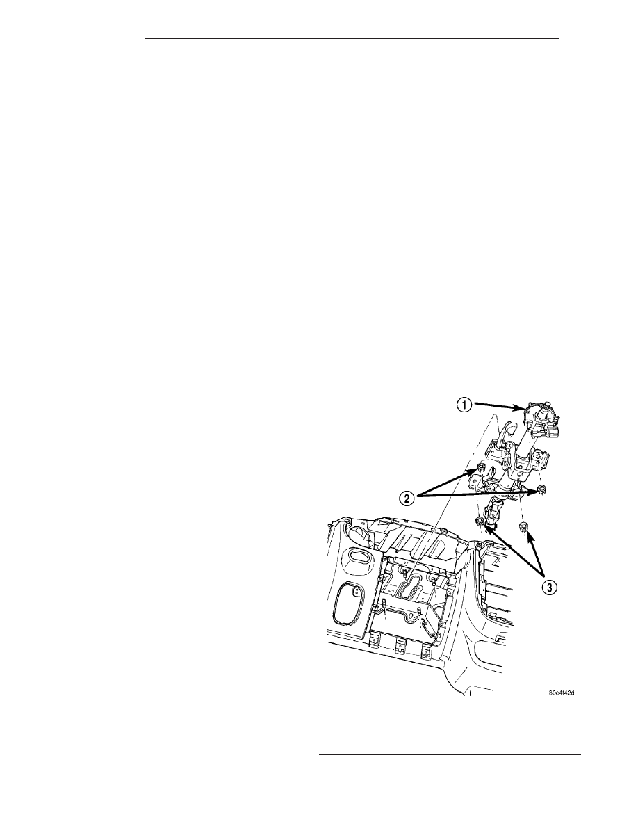
This vehicle is equipped with a tilt type steering

column. The steering column is designed to be ser-
viced only as complete assembly if an internal com-
ponent is found to be defective (Fig. 1). The shaft,
bearings and upper coupling are all serviced with the
column.

The replaceable components on the steering col-

umn assembly are:

• The key cylinder

• The ignition switch

• The multi-function switch

• The clockspring

• The trim shrouds

• The steering wheel

• The driver airbag module
These components can be serviced without removal

of the steering column from the vehicle. Refer to the
appropriate section for servicing these components
separately.

OPERATION

Turning of the steering wheel is transferred

through the steering column, upper and lower cou-
plings to the power steering gear. The gear then
moves the steering knuckles, steering the vehicle.

Fig. 1 Steering Column

1 - STEERING COLUMN
2 - UPPER MOUNTING NUTS
3 - LOWER MOUNTING NUTS

19 - 10

COLUMN

PT

The steering column used on vehicle’s equipped

with a manual transaxle has an anti-theft provision.
With the key/lock cylinder turned to the LOCK posi-
tion, and the key removed, the steering shaft (and
steering wheel) cannot be turned more than 180
degrees before locking. Vehicles equipped with an
automatic transaxle do not have this feature.

WARNING

WARNINGS AND CAUTIONS

WARNING: SAFETY GOGGLES SHOULD BE WORN
AT ALL TIMES WHEN WORKING ON STEERING
COLUMNS.

WARNING:

BEFORE

BEGINNING ANY

SERVICE

PROCEDURES THAT INVOLVES REMOVING THE
AIR BAG. REMOVE AND ISOLATE THE NEGATIVE
(-) BATTERY CABLE (GROUND) FROM THE VEHI-
CLE BATTERY. THIS IS THE ONLY SURE WAY TO
DISABLE THE AIR BAG SYSTEM. FAILURE TO DO
THIS COULD RESULT IN ACCIDENTAL AIR BAG
DEPLOYMENT AND POSSIBLE PERSONAL INJURY.

WARNING: THE AIR BAG SYSTEM IS A SENSITIVE,
COMPLEX ELECTRO-MECHANICAL UNIT. BEFORE
ATTEMPTING TO DIAGNOSE, REMOVE OR INSTALL
THE AIR BAG SYSTEM COMPONENTS YOU MUST
FIRST DISCONNECT AND ISOLATE THE BATTERY
NEGATIVE (GROUND) CABLE. FAILURE TO DO SO
COULD RESULT IN ACCIDENTAL DEPLOYMENT OF
THE AIR BAG AND POSSIBLE PERSONAL INJURY.
THE FASTENERS, SCREWS, AND BOLTS, ORIGI-
NALLY USED FOR THE AIR BAG COMPONENTS,
HAVE SPECIAL COATINGS AND ARE SPECIFI-
CALLY DESIGNED FOR THE AIR BAG SYSTEM.
THEY MUST NEVER BE REPLACED WITH ANY SUB-
STITUTES.

ANYTIME

A

NEW

FASTENER

IS

NEEDED, REPLACE WITH THE CORRECT FASTEN-
ERS PROVIDED IN THE SERVICE PACKAGE OR
FASTENERS

LISTED

IN

THE

PARTS

BOOKS.

BEFORE

SERVICING

A

STEERING

COLUMN

EQUIPPED WITH AN AIR BAG, (Refer to 8 - ELEC-
TRICAL/RESTRAINTS - WARNING).

WARNING: WHEN HANDLING AN UNDEPLOYED AIR
BAG MODULE DURING SERVICING OF THE STEER-
ING COLUMN, THE FOLLOWING PRECAUTIONS
SHOULD BE OBSERVED:

AT NO TIME SHOULD ANY SOURCE OF ELEC-

TRICITY BE PERMITTED NEAR THE INFLATOR ON
THE BACK OF THE AIR BAG MODULE.

WHEN CARRYING A LIVE MODULE, THE TRIM

COVER SHOULD BE POINTED AWAY FROM THE
BODY TO

MINIMIZE

INJURY IF

THE

MODULE

SHOULD ACCIDENTLY DEPLOY.

IF THE AIR BAG MODULE IS PLACED ON A

BENCH

OR

OTHER

SURFACE,

THE

PLASTIC

COVER SHOULD BE FACE-UP TO MINIMIZE MOVE-
MENT, IN CASE OF ACCIDENTAL DEPLOYMENT.

CAUTION: Disconnect negative (ground) cable from
the battery before servicing any column compo-
nent.

CAUTION: Do not attempt to remove the pivot pins
to disassemble the tilting mechanism. Damage will
occur.

DIAGNOSIS AND TESTING - STEERING
COLUMN

For diagnosis of conditions relating to the steering

column, (Refer to 19 - STEERING - DIAGNOSIS
AND TESTING).

REMOVAL

REMOVAL

NOTE: Before proceeding, (Refer to 19 - STEERING/
COLUMN - WARNING).

WARNING: WHEN AN UNDEPLOYED AIRBAG MOD-
ULE IS TO BE REMOVED FROM THE STEERING
WHEEL,

FIRST

DISCONNECT

THE

BATTERY

GROUND CABLE AND ISOLATE IT. ALLOW THE
SYSTEM CAPACITOR TO DISCHARGE FOR A MINI-
MUM OF TWO MINUTES, THEN BEGIN THE AIRBAG
REMOVAL.

(1) Disconnect the negative (-) cable from the bat-

tery and isolate the cable.

(2) Before beginning removal of the steering col-

umn, be sure the front wheels of vehicle are in the
STRAIGHT-AHEAD position.

(3) Remove the ignition key from the ignition key

cylinder.

(4) Remove the silencer pad below the knee

blocker panel below the steering column.

(5) Fold down and remove the knee blocker.

PT

COLUMN

19 - 11

COLUMN (Continued)

(6) Remove the two screws attaching the lower

shroud to the steering column and upper shroud (Fig.
2). After removing the screws, unclip the shrouds
from each other by applying hand pressure along the
seams where the shrouds connect on the sides, then
remove the lower shroud from the upper shroud and
column. Remove the upper shroud from the steering
column.

(7) Use the following to properly remove the air

bag module from the column:

(a) Using a pair of 90° internal snap ring pliers

or equivalent, pry open the retaining clip (Fig. 3)
at the top rear of the steering wheel to release the
top retaining pin (Fig. 4). Pull or press rearward
on the airbag module while doing this. The pin will
disengage.

(b) Using a pair of 90° internal snap ring pliers

or equivalent, pry open the retaining clip (Fig. 5)
at the bottom rear of the steering wheel and at he
same time gently pry the pin away from the retain-
ing clip using a pocket screwdriver or equivalent,
so it can slide through the middle of the clip. Use
the screwdriver to push the pin through the clip.

(c) Pull the module outward enough to expose

the wire harness connections. Disconnect the two
harness connectors on the module (squib and horn
feed) (Fig. 6).

(d) Remove the airbag module from the vehicle.

(8) Disconnect the speed control switch wiring har-

ness connector (Fig. 6).

(9) Holding the steering wheel firmly in place,

remove the steering wheel retaining bolt from the
steering column shaft in the center of the steering
wheel (Fig. 6).

Fig. 2 Steering Column Shrouds

1 - UPPER SHROUD
2 - LOWER SHROUD
3 - MOUNTING SCREWS

Fig. 3 Driver Airbag Pin Retaining Clip

Fig. 4 Upper Driver Airbag Pin Retaining Clip

Removal/Installation

Fig. 5 Lower Driver Airbag Pin Retaining Clip

Removal/Installation

19 - 12

COLUMN

PT

COLUMN (Continued)

CAUTION: When installing a wheel puller on the
steering wheel, be sure the puller bolts are fully
seated in the threaded holes on the steering wheel.
If the bolts are not fully seated in the threaded
holes, the threads may be stripped out of the steer-
ing wheel when attempting to remove the steering
wheel. Take care not to over-thread the puller bolts
such that they contact the clockspring possibly
damaging it.
Also, threading the retaining bolt back in the end of
the shaft until approximately 13 mm (0.5 in.) of
thread is showing between the wheel and the head
of the bolt allows a safe reaction surface for the
puller to work against.

(10) Thread the wheel retaining bolt back into the

end of the shaft until approximately 13 mm (0.5 in.)
of thread is showing between the wheel and the head
of the bolt.

(11) Install a steering wheel puller on the steering

wheel.

CAUTION: Do not bump or hammer on steering
wheel or steering column shaft when removing
steering wheel from steering column.

(12) Holding the steering wheel firmly in the

STRAIGHT-AHEAD position, remove steering wheel
from the steering column shaft using the puller.
Remove the wheel retaining bolt and the steering
wheel.

(13) At the base of the column, remove the steer-

ing column coupling retainer pin, back off the pinch
bolt nut, and remove the steering column coupling
pinch bolt (Fig. 7) (the pinch bolt nut is caged to the
coupling and is not removable). Separate the upper
and lower steering column couplings.

(14) If the vehicle is equipped with a automatic

transaxle, disconnect the automatic transaxle igni-
tion

interlock

cable

from

the

steering

column.

Depress the tab on top of the cable connector and
remove the cable from the back side of the steering
column ignition cylinder housing (Fig. 8).

NOTE: If the same steering column is to be rein-
stalled, clamp the tilt lever to lock the column in
place so that it can be easily reinstalled in the same
orientation.

(15) Remove the two lower mounting nuts attach-

ing the steering column to the instrument panel (Fig.
9).

(16) Remove the two upper mounting nuts attach-

ing the steering column to the instrument panel (Fig.
9).

(17) Lower the steering column away from the

instrument panel.

Fig. 6 Electrical Connectors

1 - STEERING WHEEL RETAINING BOLT
2 - SPEED CONTROL SWITCH CONNECTOR
3 - HORN SWITCH CONNECTOR
4 - AIRBAG CONNECTOR

Fig. 7 Coupling Connection

1 - RETAINING PIN
2 - PINCH BOLT
3 - NUT

PT

COLUMN

19 - 13

COLUMN (Continued)


Content   ..  746  747  748  749   ..