Chrysler PT Cruiser. Manual - part 705


  Index      Chrysler     Chrysler PT Cruiser - service repair manual 2005 year


Search            


Content   ..  703  704  705  706   ..


Chrysler PT Cruiser. Manual - part 705


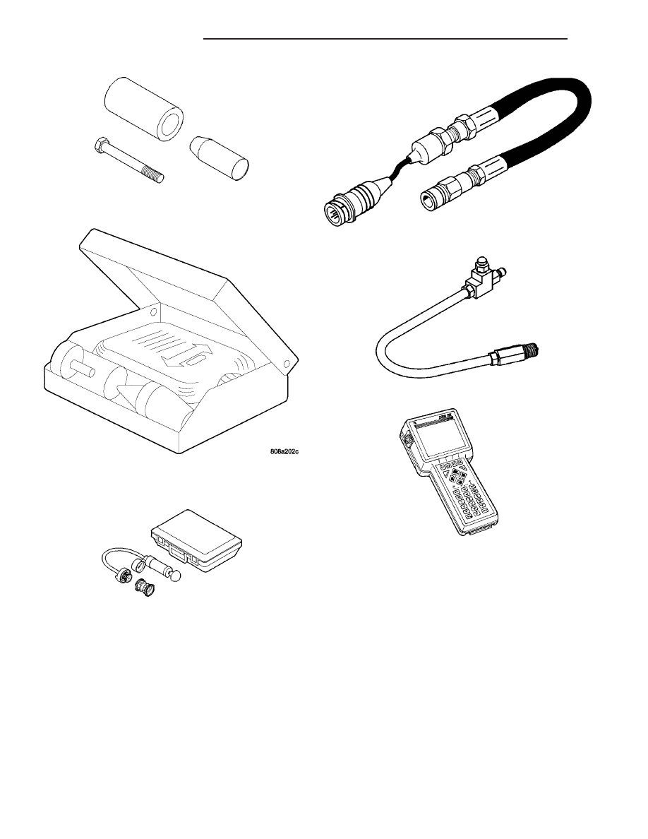
Front Crankshaft Oil Seal Installer 6780

Combustion Leak Tester C-3685-A

Cooling System Tester 7700

Pressure Transducer CH7059

Cylinder Compression Pressure Adaptor 8116

DRB III

T

with PEP Module OT-CH6010A

9 - 100

ENGINE 2.4L DOHC

PT

ENGINE 2.4L DOHC (Continued)

AIR CLEANER ELEMENT

REMOVAL

(1) Unfasten clasps on sides of air cleaner housing

cover. Lift cover off air cleaner housing (Fig. 19).

(2) Remove filter element.
(3) If necessary, clean the inside of the air cleaner

housing.

INSTALLATION

(1) Install new filter element.
(2) Place cover over air cleaner housing. Snap

clasps in place.

AIR CLEANER HOUSING

REMOVAL

(1) Disconnect the throttle body air inlet hose/

clean air hose from the air cleaner housing (Fig. 20)
or (Fig. 21) and (Fig. 22).

(2) Pull air cleaner housing straight up to remove.
(3) Remove the inlet duct from the air cleaner

housing.

INSTALLATION

(1) Install inlet duct to the air cleaner housing.
(2) Make sure the rubber grommets, for the air

cleaner housing lower pins, are in place when rein-
stalling the air cleaner housing. The rubber grom-
mets mount to the PDC bracket (Fig. 20) or (Fig. 21).

(3) Push air cleaner housing down while aligning

pins into the grommets.

(4) Connect the throttle body air inlet hose/clean

air hose to the air cleaner housing (Fig. 20) or (Fig.
21) and (Fig. 22).

Fig. 19 Air Cleaner Cover

Fig. 20 Air Inlet System

Fig. 21 Air Inlet System - 2.4L Turbo

1 - CLEAN AIR HOSE
2 - AIR CLEANER HOUSING
3 - FRESH AIR INLET DUCT
4 - PDC MOUNTING BRACKET

PT

ENGINE 2.4L DOHC

9 - 101

CYLINDER HEAD

DESCRIPTION

The cross flow designed, aluminum cylinder head

contains dual over-head camshafts with four valves
per cylinder (Fig. 23). The valves are arranged in two
in-line banks. The intake valves face toward the
front of the vehicle. The exhaust valves face the dash
panel. The cylinder head incorporates powdered
metal valve guides and seats. The cylinder head is
sealed to the block using a multi-layer steel head
gasket and retaining bolts.

Integral oil galleries provide lubrication passages

to the hydraulic lash adjusters, camshafts, and valve
mechanisms.

DIAGNOSIS AND TESTING

CYLINDER HEAD GASKET

A cylinder head gasket leak can be located between

adjacent cylinders or between a cylinder and the
adjacent water jacket.

Possible indications of the cylinder head gasket

leaking between adjacent cylinders are:

• Loss of engine power

• Engine misfiring

• Poor fuel economy

Possible indications of the cylinder head gasket

leaking between a cylinder and an adjacent water
jacket are:

• Engine overheating

• Loss of coolant

• Excessive steam (white smoke) emitting from

exhaust

• Coolant foaming

CYLINDER-TO-CYLINDER LEAKAGE TEST

To determine if an engine cylinder head gasket is

leaking between adjacent cylinders, follow the proce-
dures in Cylinder Compression Pressure Test (Refer
to 9 - ENGINE - DIAGNOSIS AND TESTING). An
engine cylinder head gasket leaking between adja-
cent cylinders will result in approximately a 50–70%
reduction in compression pressure.

CYLINDER-TO-WATER JACKET LEAKAGE TEST

WARNING: USE EXTREME CAUTION WHEN THE
ENGINE IS OPERATING WITH COOLANT PRES-
SURE CAP REMOVED.

VISUAL TEST METHOD

With the engine cool, remove the coolant pressure

cap. Start the engine and allow it to warm up until
thermostat opens.

Fig. 22 Clean Air Hose - 2.4L Turbo

1 - CLEAN AIR HOSE
2 - TURBOCHARGER

Fig. 23 Cylinder Head and Camshafts

1 - CAMSHAFT BEARING CAPS
2 - PLUG
3 - CAMSHAFT
4 - CYLINDER HEAD
5 - CAMSHAFT OIL SEAL

9 - 102

ENGINE 2.4L DOHC

PT

AIR CLEANER HOUSING (Continued)

If a large combustion/compression pressure leak

exists, bubbles will be visible in the coolant.

COOLING SYSTEM TESTER METHOD

WARNING: WITH COOLING SYSTEM TESTER IN
PLACE, PRESSURE WILL BUILD UP FAST. EXCES-
SIVE

PRESSURE

BUILT

UP,

BY

CONTINUOUS

ENGINE OPERATION, MUST BE RELEASED TO A
SAFE PRESSURE POINT. NEVER PERMIT PRES-
SURE TO EXCEED 138 kPa (20 psi).

Install Cooling System Tester 7700 or equivalent to

pressure cap neck. Start the engine and observe the
tester’s pressure gauge. If gauge pulsates with every
power stroke of a cylinder a combustion pressure
leak is evident.

CHEMICAL TEST METHOD

Combustion leaks into the cooling system can also

be checked by using Bloc-Chek Kit C-3685-A or
equivalent. Perform test following the procedures
supplied with the tool kit.

REMOVAL - CYLINDER HEAD

(1) Perform fuel system pressure release procedure

before attempting any repairs (Refer to 14 -
FUEL SYSTEM/FUEL DELIVERY - STANDARD
PROCEDURE).

(2) Remove clean air hose and air cleaner housing

(Refer to 9 - ENGINE/AIR INTAKE SYSTEM/AIR
CLEANER HOUSING - REMOVAL).

(3) Disconnect negative cable from battery.
(4) Drain cooling system (Refer to 7 - COOLING/

ENGINE - STANDARD PROCEDURE).

(5) Remove upper intake manifold (Refer to 9 -

ENGINE/MANIFOLDS/INTAKE

MANIFOLD

-

REMOVAL).

(6) Remove fastener attaching dipstick tube to

lower intake manifold (Fig. 24) or (Fig. 25).

(7) Turbocharger equipped vehicles: Remove

lower intake manifold support bracket (Fig. 25).

(8) Disconnect the fuel supply line quick-connect at

the fuel rail assembly (Refer to 14 - FUEL SYSTEM/
FUEL DELIVERY/QUICK CONNECT FITTING -
STANDARD PROCEDURE).

(9) Remove heater tube support bracket from cyl-

inder head.

(10) Remove

upper

radiator

hose.

Disconnect

heater hoses from thermostat housing.

(11) Disconnect engine coolant temperature sensor

connector.

(12) Remove accessory drive belts (Refer to 7 -

COOLING/ACCESSORY

DRIVE/DRIVE

BELTS

-

REMOVAL).

(13) Disconnect exhaust pipe from manifold.
(14) Turbocharger equipped vehicles: (Fig. 26)

• Remove turbocharger heat shields

• Remove elbow support bracket

Fig. 24 Dipstick Tube

1 - DIPSTICK TUBE
2 - SCREW

Fig. 25 Lower Intake Manifold Support Bracket -

2.4L Turbo

1 - UPPER INTAKE MANIFOLD
2 - LOWER INTAKE MANIFOLD
3 - SUPPORT BRACKET
4 - DIPSTICK TUBE SCREW

PT

ENGINE 2.4L DOHC

9 - 103

CYLINDER HEAD (Continued)


Content   ..  703  704  705  706   ..