Chrysler PT Cruiser. Manual - part 520


  Index      Chrysler     Chrysler PT Cruiser - service repair manual 2005 year


Search            


Content   ..  518  519  520  521   ..


Chrysler PT Cruiser. Manual - part 520


PASSENGER AIRBAG

DESCRIPTION

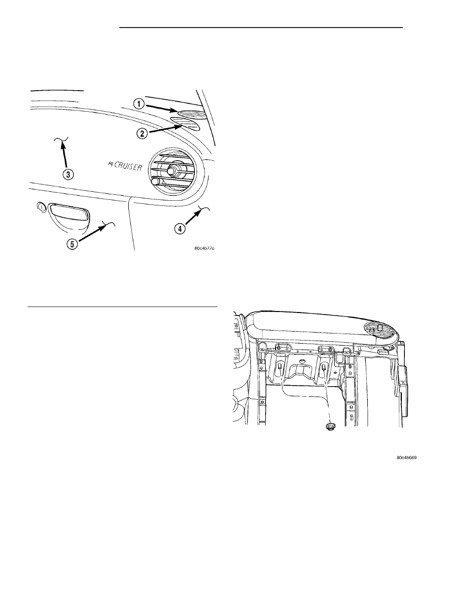
The passenger airbag is located behind the passen-

ger airbag cover, between the glove box and instru-
ment panel top cover (Fig. 27).

The passenger airbag includes a stamped steel

housing within which the cushion and inflator are
mounted and sealed. Two stamped metal brackets,
one on each end of the housing, enclose the cushion
and inflator. The mounting scheme consists of two
weld studs and a bracket with two tabs off the bot-
tom of the housing.

Following a passenger airbag deployment, the pas-

senger airbag and the passenger airbag cover must
be replaced. If inspection reveals that the passenger
airbag mounting points on the instrument panel
structural duct have been cracked or damaged, the
instrument panel assembly must also be replaced.
The passenger airbag cannot be repaired, and must
be replaced if deployed or in any way damaged.

OPERATION

The hybrid-type inflator assembly includes a small

canister of highly compressed argon gas. The inflator
seals the hole in the airbag cushion so it can dis-
charge the gas it produces directly into the cushion
when supplied with the proper electrical signal. Fol-
lowing an airbag deployment, the airbag cushion
quickly deflates by venting this gas through the

porous fabric material used on each end panel of the
airbag cushion.

The passenger airbag is secured with screws to the

instrument panel structural duct beneath the instru-
ment panel top pad and above the glove box opening.

REMOVAL

NON-DEPLOYED AIRBAG

(1) Open hood.
(2) Disconnect and isolate the battery negative

cable.

(3) Wait two minutes for the system reserve capac-

itor to discharge before servicing any airbag compo-
nents.

(4) Remove instrument panel top cover (Refer to

23 - BODY/INSTRUMENT PANEL/INSTRUMENT
PANEL TOP COVER - REMOVAL).

(5) Open glove box, push in on the box/bin sides

and lower to floor.

(6) Remove the right instrument panel end cap.
(7) Remove four passenger airbag cover screws

along the bottom end of the airbag cover.

(8) Remove two passenger airbag cover screws

along the top edge of the airbag cover.

(9) Remove two nuts retaining passenger airbag to

instrument panel assembly inside glove box opening
(Fig. 28).

(10) Lift airbag up until the wire connector is vis-

ible and disconnect the wire connector from airbag.
Unlock the locking tab (Fig. 29) and release the con-
nector (Fig. 30).

(11) Remove passenger airbag from vehicle.

Fig. 27 PASSENGER AIRBAG LOCATION

1 - INSTRUMENT PANEL SPEAKER
2 - SIDE WINDOW DEMISTER
3 - PASSENGER AIRBAG
4 - RIGHT INSTRUMENT PANEL END COVER
5 - GLOVE BOX ASSEMBLY

Fig. 28 PASSENGER AIRBAG RETAINING NUTS

8O - 16

RESTRAINTS

PT

DEPLOYED AIRBAG

(1) Open hood.
(2) Disconnect and isolate the battery negative

cable.

(3) Roll/fold airbag towards instrument panel.
(4) Close door over folded airbag and tape door

closed.

(5) Remove instrument panel top cover (Refer to

23 - BODY/INSTRUMENT PANEL/INSTRUMENT
PANEL TOP COVER - REMOVAL).

(6) Open glove box, push in on the box/bin sides

and lower to floor.

(7) Remove the right instrument panel end cap.
(8) Remove four passenger airbag cover screws

along the bottom end of the airbag cover.

(9) Remove two passenger airbag cover screws

along the top edge of the airbag cover.

(10) Remove two nuts retaining passenger airbag

to instrument panel assembly inside glove box open-
ing (Fig. 28).

(11) Lift airbag up until the wire connector is vis-

ible and disconnect the wire connector from airbag.
Unlock the locking tab and release the connector
(Fig. 30).

(12) Remove passenger airbag from vehicle.

INSTALLATION

(1) Place airbag into instrument panel opening,

connect the 4-way wire connector, and lock the red
locking tab (Fig. 30).

(2) Install the two nuts retaining passenger airbag

to instrument panel assembly inside glove box open-
ing (Fig. 28). Torque the two airbag retaining nuts to
22 to 34 N·m (200 to 300 in. lbs.) torque.

(3) Install two passenger airbag cover screws along

the top edge of the airbag cover. Torque trim screws
to 2 N·m (20 in. lbs.).

(4) Install four passenger airbag cover screws

along the bottom end of the airbag cover. Torque trim
screws to 2 N·m (20 in. lbs.).

(5) Install the right instrument panel end cap.
(6) Push in on the box/bin sides and close glove

box door.

(7) Install instrument panel top cover (Refer to 23

-

BODY/INSTRUMENT

PANEL/INSTRUMENT

PANEL TOP COVER - INSTALLATION).

WARNING: DO NOT CONNECT BATTERY NEGATIVE
CABLE YET (Refer to 8 - ELECTRICAL/RESTRAINTS
- DIAGNOSIS AND TESTING - AIRBAG SYSTEM).

(8) Close hood.
(9) Verify vehicle and system operation.

Fig. 29 ELECTRICAL CONNECTOR LOCK

1 - LOCKING TAB

Fig. 30 PASSENGER AIRBAG ELECTRICAL

CONNECTOR

1 - ELECTRICAL CONNECTOR
2 - PASSENGER AIRBAG

PT

RESTRAINTS

8O - 17

PASSENGER AIRBAG (Continued)

PASSENGER AIRBAG COVER

REMOVAL

(1) Open hood.
(2) Disconnect and isolate the battery negative

cable.

(3) Wait two minutes for the system reserve capac-

itor to discharge before servicing any airbag compo-
nents.

(4) Remove the passenger airbag from the vehicle

(Refer to 8 - ELECTRICAL/RESTRAINTS/PASSEN-
GER AIRBAG - REMOVAL).

(5) Unsnap

cover

from

passenger

airbag

and

remove by lifting the airbag cover up towards the
hinge.

(6) Reach in under the cover and push down on

the metal flap running the length of the top of the
airbag housing.

(7) Maneuver airbag cover out of the airbag hous-

ing.

INSTALLATION

If reinstalling the airbag cover onto the same pas-

senger airbag, perform the following adjustment.
Otherwise, go to Step 1.

• Using a 90° needle nose pliers or equivalent,

place the pliers on the rear edge of the airbag cover
metal flap retainer.

• Bend roughly 10° so that the metal flap is closed

slightly to eliminate rattles of the airbag cover.

• Bend until the measurement of the metal flap to

airbag housing is 7 - 8.3 mm (use a drill bit ranging
from 9/32 - 21/64 inch).

(1) Snap cover onto the passenger airbag frame.
(2) Install the passenger airbag (Refer to 8 -

ELECTRICAL/RESTRAINTS/PASSENGER AIRBAG
- INSTALLATION).

WARNING: DO NOT CONNECT BATTERY NEGATIVE
CABLE YET (Refer to 8 - ELECTRICAL/RESTRAINTS
- DIAGNOSIS AND TESTING - AIRBAG SYSTEM).

(3) Close hood.
(4) Verify vehicle and system operation.

REAR CENTER SEAT BELT &
RETRACTOR

REMOVAL

(1) Detach Quick Connect Anchor by depressing

tab.

(2) Remove seat bezel.
(3) De-trim seat back upper (Refer to 23 - BODY/

SEATS/SEAT BACK COVER - REMOVAL).

(4) Lock seat back latch.

(5) Disconnect Locking Cable from retractor.
(6) Remove retractor bolt.
(7) Feed webbing and hardware through seat

frame and remove retractor.

INSTALLATION

(1) Feed webbing and hardware through seat

frame and install retractor.

(2) Install retractor bolt and tighten to 40 N·m (30

ft. lbs.).

(3) Connect locking cable to retractor.
(4) Unlock seat back latch.
(5) Re-trim rear seat back cover (Refer to 23 -

BODY/SEATS/SEAT BACK COVER - INSTALLA-
TION).

(6) Install seat bezel.
(7) Attach Quick Connect Anchor.

REAR SEAT BELT &
RETRACTOR

REMOVAL

(1) Remove turning loop cover.
(2) Remove turning loop bolt.
(3) Remove upper and lower trim bezels.
(4) Remove trim panel from body (Refer to 23 -

BODY/INTERIOR/LEFT QUARTER TRIM PANEL -
REMOVAL).

(5) Remove lower seat belt anchor bolt.
(6) Feed seat belt and hardware through trim

openings.

(7) Unbolt and remove the retractor and belt

assembly.

INSTALLATION

(1) Place rear seat belt retractor into position.
(2) Install bolt attaching retractor. Tighten the

retractor belt bolt to 40 N·m (30 ft. lbs.) torque.

(3) Feed seat belt and hardware through trim

opening.

(4) Install lower seat belt anchor bolt. Tighten to

40 N·m (30 ft. lbs.).

(5) Install trim panel (Refer to 23 - BODY/INTE-

RIOR/LEFT QUARTER TRIM PANEL - INSTALLA-
TION).

(6) Install upper and lower trim bezels.
(7) Install turning loop bolts.
(8) Install turning loop cover.

8O - 18

RESTRAINTS

PT

REAR SEAT BELT &
RETRACTOR - PT27

REMOVAL

(1) Release hood latch and open hood.
(2) Disconnect and isolate the battery negative

cable.

WARNING: Wait two minutes for the airbag system
reserve capacitor to discharge before beginning
any airbag system or component service. Failure to
do so may result in accidental airbag deployment,
personal injury or death.

(3) Remove the lower seat belt anchor nut (Fig.

31).

(4) Remove the Lower Quarter Trim Panel the side

in which you are removing the seat belt and retrac-
tor.

(5) Remove the four bolts to the rear seat upper

bolster.

(6) Feed the seat belt webbing through the top of

the bolster.

(7) Remove the one retaining bolt to the seat belt

retractor (Fig. 32).

(8) Remove seat belt & retractor from vehicle.

INSTALLATION

(1) Position seat belt & retractor into vehicle.
(2) Install the one retaining bolt to the seat belt

retractor (Fig. 32). Torque bolt to 40 N·m (30 ft. lbs.).

(3) Feed the seat belt webbing through the top of

the rear seat upper bolster.

(4) Install the four bolts to the rear seat upper bol-

ster.

(5) Install the Lower Quarter Trim Panel.
(6) Install the lower seat belt anchor nut (Fig. 31).

Torque bolt to 40 N·m (30 ft. lbs.).

(7) Connect the battery negative cable.
(8) Close hood.
(9) Verify vehicle and system operation.

REAR SEAT BELT BUCKLE

REMOVAL

The rear seat belt buckles are riveted to the rear

seat lower pivot. To service the rear seat belt buckles,
the entire pivot assembly needs to be replaced.

REAR SEAT BELT BUCKLE -
PT27

REMOVAL

(1) Open door and decklid.
(2) Release the fold down rear seat and pull for-

ward.

(3) Remove the two screws at the side of the seat

cushion shield at the buckle area (Fig. 33).

(4) Remove the two screws at the bottom of the

cushion cover (Fig. 33).

Fig. 31 SEAT BELT ANCHOR NUT - REMOVE/

INSTALL

1 - SEAT BELT ANCHOR NUT

Fig. 32 SEAT BELT & RETRACTOR - REMOVE/

INSTALL

1 - SEAT BELT & RETRACTOR
2 - SEAT BELT RETRACTOR RETAINING BOLT

PT

RESTRAINTS

8O - 19


Content   ..  518  519  520  521   ..