Chrysler PT Cruiser. Manual - part 494


  Index      Chrysler     Chrysler PT Cruiser - service repair manual 2005 year


Search            


Content   ..  492  493  494  495   ..


Chrysler PT Cruiser. Manual - part 494


AUTO SHUT DOWN RELAY

DESCRIPTION

The relay is located in the Power Distribution Cen-

ter (PDC). For the location of the relay within the
PDC, refer to the PDC cover for location. Check elec-
trical terminals for corrosion and repair as necessary

OPERATION

The

engine

switched

battery

(NGC

vehicles)

informs the PCM when the ASD relay energizes. A 12
volt signal at this input indicates to the PCM that
the ASD has been activated. This input is also used
to power certain drivers on NGC vehicles.

When energized, the ASD relay on NGC vehicles

provides power to operate the injectors, ignition coil,
generator field, O2 sensor heaters (both upstream
and downstream), evaporative purge solenoid, EGR
solenoid

(if

equipped)

wastegate

solenoid

(if

equipped), and NVLD solenoid (if equipped).

The ASD relay also provides a sense circuit to the

PCM for diagnostic purposes. If the PCM does not
receive 12 volts from this input after grounding the
control side of the ASD relay, it sets a Diagnostic
Trouble Code (DTC). The PCM energizes the ASD
any time there is an engine speed that exceeds a pre-
determined value (typically about 50 rpm). The ASD
relay can also be energized after the engine has been
turned off to perform an O2 sensor heater test, if
vehicle is equipped with OBD II diagnostics.

As mentioned earlier, the PCM energizes the ASD

relay during an O2 sensor heater test. On NGC vehi-
cles it checks the O2 heater upon vehicle start. The
PCM still operates internally to perform several
checks, including monitoring the O2 sensor heaters.

CAMSHAFT POSITION
SENSOR

DESCRIPTION

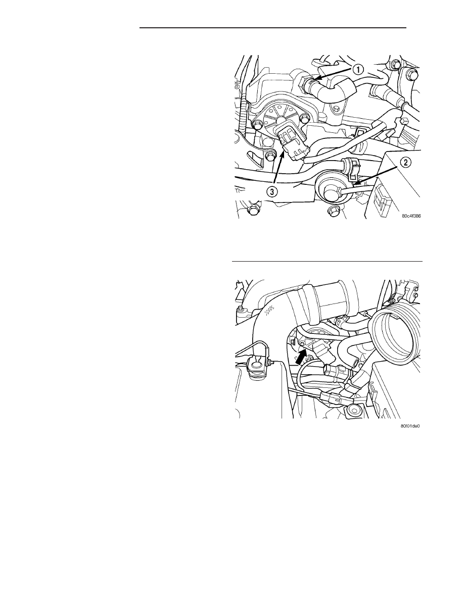
On 2.0/2.4L engines the camshaft position sensor is

mounted to the rear of the cylinder head (Fig. 1),
(Fig. 2),.

OPERATION

The PCM sends approximately 5 volts to the Hall-

effect sensor. This voltage is required to operate the
Hall-effect chip and the electronics inside the sensor.
The input to the PCM occurs on a 5 volt output ref-
erence circuit. A ground for the sensor is provided
through the sensor return circuit. The PCM identifies
camshaft position by registering the change from 5 to
0 volts, as signaled from the Camshaft Position sen-
sor (Fig. 3).

On 2.0/2.4L engines a target magnet attaches to

the rear of the camshaft and indexes to the correct
position. The target magnet has fourteen different
poles arranged in an asymmetrical pattern. As the
target magnet rotates, the camshaft position sensor
senses the change in polarity (Fig. 4).

The PCM determines fuel injection synchronization

and cylinder identification from inputs provided by
the camshaft position sensor (Fig. 1) and crankshaft
position sensor. From the two inputs, the PCM deter-
mines crankshaft position.

Fig. 1 Camshaft Position Sensor -2.0/2.4L DOHC

1 - PCV VALVE
2 - EGR VALVE
3 - CAMSHAFT POSITION SENSOR

Fig. 2 CAMSHAFT POSITION SENSOR - 2.4L TURBO

8I - 4

IGNITION CONTROL

PT

The sensor input switches from high (5 volts) to

low (0.30 volts) as the target magnet rotates. When
the north pole of the target magnet passes under the
sensor, the output switches high. The sensor output
switches low when the south pole of the target mag-
net passes underneath.

REMOVAL

REMOVAL - 2.0/2.4L

(1) Remove the air cleaner lid, disconnect the inlet

air temperature sensor and makeup air hose.

(2) Remove the negative battery cable.
(3) Disconnect electrical connector from camshaft

position sensor.

(4) Remove camshaft position sensor mounting

screws. Remove sensor.

(5) Loosen screw attaching target magnet to rear

of camshaft (Fig. 5).

REMOVAL - 1.6L

(1) Disconnect the negative battery cable.
(2) Relocate the power steering return hose.
(3) Disconnect the electrical connector from the

camshaft sensor.

(4) Remove 1 screws from sensor.
(5) Remove sensor (Fig. 6).

Fig. 3 Target Magnet - Typical

1 - CAM MAGNET/TARGET
2 - CAMSHAFT POSITION SENSOR

Fig. 4 Target Magnet Polarity - NGC

1 - TARGET MAGNET

Fig. 5 Target Magnet Removal/Installation

1 - CAM MAGNET/TARGET
2 - CAMSHAFT POSITION SENSOR

PT

IGNITION CONTROL

8I - 5

CAMSHAFT POSITION SENSOR (Continued)

INSTALLATION

INSTALLATION - 2.0/2.4L

The target magnet has locating dowels that fit into

machined locating holes in the end of the camshaft
(Fig. 7).

(1) Install target magnet in end of camshaft.

Tighten mounting screw to 3.6 N·m (32 ±5 in. lbs.)
torque. Over torquing could cause cracks in magnet.
If magnet cracks replace it.

(2) Install camshaft position sensor. Tighten sensor

mounting screws to 9 N·m (80 ±15 in. lbs.) torque.

(3) Carefully attach electrical connector to cam-

shaft position sensor. Installation at an angle may
damage the sensor pins.

(4) Install the negative battery cable.
(5) Install the air cleaner lid, connect the inlet air

temperature sensor and makeup air hose.

INSTALLATION - 1.6L

(1) Install sensor to cylinder head (Fig. 6).
(2) Tighten screws to 9 N·m (80 in. lbs.).
(3) Connect the electrical connector to the sensor.
(4) Relocate the power steering return line.
(5) Connect the negative battery cable

IGNITION COIL

DESCRIPTION

WARNING: THE DIRECT IGNITION SYSTEM GENER-
ATES APPROXIMATELY 40,000 VOLTS. PERSONAL
INJURY COULD RESULT FROM CONTACT WITH
THIS SYSTEM.

The coil pack consists of 2 coils molded together.

The coil pack is mounted on the valve cover (Fig. 8)
or (Fig. 9).

OPERATION

WARNING: THE DIRECT IGNITION SYSTEM GENER-
ATES APPROXIMATELY 40,000 VOLTS. PERSONAL
INJURY COULD RESULT FROM CONTACT WITH
THIS SYSTEM.

High tension leads route to each cylinder from the

coil. The coil fires two spark plugs every power
stroke. One plug is the cylinder under compression,
the other cylinder fires on the exhaust stroke. Coil
number one fires cylinders 1 and 4. Coil number two
fires cylinders 2 and 3. The PCM determines which
of the coils to charge and fire at the correct time.

Fig. 6 CAMSHAFT SENSOR LOCATION

Fig. 7 Target Magnet Installation

1 - LOCATING DOWELS
2 - LOCATING HOLES (2)

Fig. 8 Ignition Coil Pack—2.0/2.4L

8I - 6

IGNITION CONTROL

PT

CAMSHAFT POSITION SENSOR (Continued)

The Auto Shutdown (ASD) relay provides battery

voltage to the ignition coil. The PCM provides a
ground contact (circuit) for energizing the coil. When
the PCM breaks the contact, the energy in the coil
primary transfers to the secondary causing the
spark. The PCM will de-energize the ASD relay if it
does not receive the crankshaft position sensor and
camshaft position sensor inputs.

REMOVAL

REMOVAL - 1.6L

NOTE: The 1.6L is attached with a rubber isolator
system. Care must be exercised in retaining all the
pieces and reinstalling in the order they where
removed.

(1) Remove air cleaner assembly cover and discon-

nect the inlet air temperature sensor (Fig. 10).

(2) Disconnect the negative battery cable.
(3) Disconnect the electrical connector at the throt-

tle body.

(4) Remove the purge hose from throttle body.
(5) Remove the 4 bolts from the upper to lower

manifold (Fig. 11).

Fig. 9 IGNITION COIL LOCATION - 2.4L TURBO

Fig. 10 INLET AIR TEMP. SENSOR

Fig. 11 UPPER MANIFOLD BOLTS

PT

IGNITION CONTROL

8I - 7

IGNITION COIL (Continued)


Content   ..  492  493  494  495   ..