Chrysler PT Cruiser. Manual - part 444


  Index      Chrysler     Chrysler PT Cruiser - service repair manual 2005 year


Search            


Content   ..  442  443  444  445   ..


Chrysler PT Cruiser. Manual - part 444


INSTALLATION

(1) The pivot ball pocket in the lever, as well as

the lever arms should be lubricated with grease prior
to installation.

(2) Assemble the lever to the bearing (Fig. 30). The

small pegs on the bearing must go over the lever
arms.

(3) Slide the bearing and lever assembly onto the

input shaft bearing retainer, as a unit.

(4) Snap the clutch release lever onto the pivot

ball.

(5) Reinstall transaxle assembly. (Refer to 21 -

TRANSMISSION/TRANSAXLE/MANUAL - INSTAL-
LATION)

FLYWHEEL

DESCRIPTION

1.6L Equipped Models

1.6L Equipped Models utilize a conventional fly-

wheel assembly, which is a solid rotating mass fas-
tened to the rear of the crankshaft (Fig. 31). The
flywheel also incorporates an integral starter ring
gear.

2.2L Turbo Diesel Equipped Models

The Dual-Mass Flywheel (DMF) is utilized on 2.2L

TD/5-speed models. Models equipped with the turbo-
charged 2.4L Engine option also utilize a Dual-Mass
Flywheel, but it is a serviceable part of the Modular
Clutch Assembly. (Refer to 6 - CLUTCH/MODULAR
CLUTCH - DESCRIPTION). The DMF consists of
two decoupled masses (primary and secondary mass)
which are connected via a spring/damping system
(Fig. 32). The primary flywheel side is bolted to the
crankshaft. The secondary flywheel face serves as the
driving member to the clutch disc. Internal springs
between the flywheels are used to couple the masses
while dampening energy. The flywheel also incorpo-
rates the ring gear around the outer circumference to
mesh with the starter to permit engine cranking.

OPERATION

The flywheel serves to dampen the engine firing

pulses. The heavy weight of the flywheel relative to
the rotating mass of the engine components serves to
stabilize the flow of power to the remainder of the
drivetrain. The crankshaft has the tendency to
attempt to speed up and slow down in response to
the cylinder firing pulses. The flywheel dampens
these impulses by absorbing energy when the crank-
shaft speeds and releasing the energy back into the
system when the crankshaft slows down.

On a Dual Mass Flywheel, the additional second-

ary mass coupled to the transmission lowers the nat-
ural frequency of the transmission rotating elements.
This decreases the transmission gear rattle. The
damper springs between the two flywheel masses
replace the clutch disc damper springs and assist in
a smooth transfer of torque to the transmission.

CAUTION: The Dual Mass Flywheel is serviced as
an assembly only and should never be disassem-
bled.

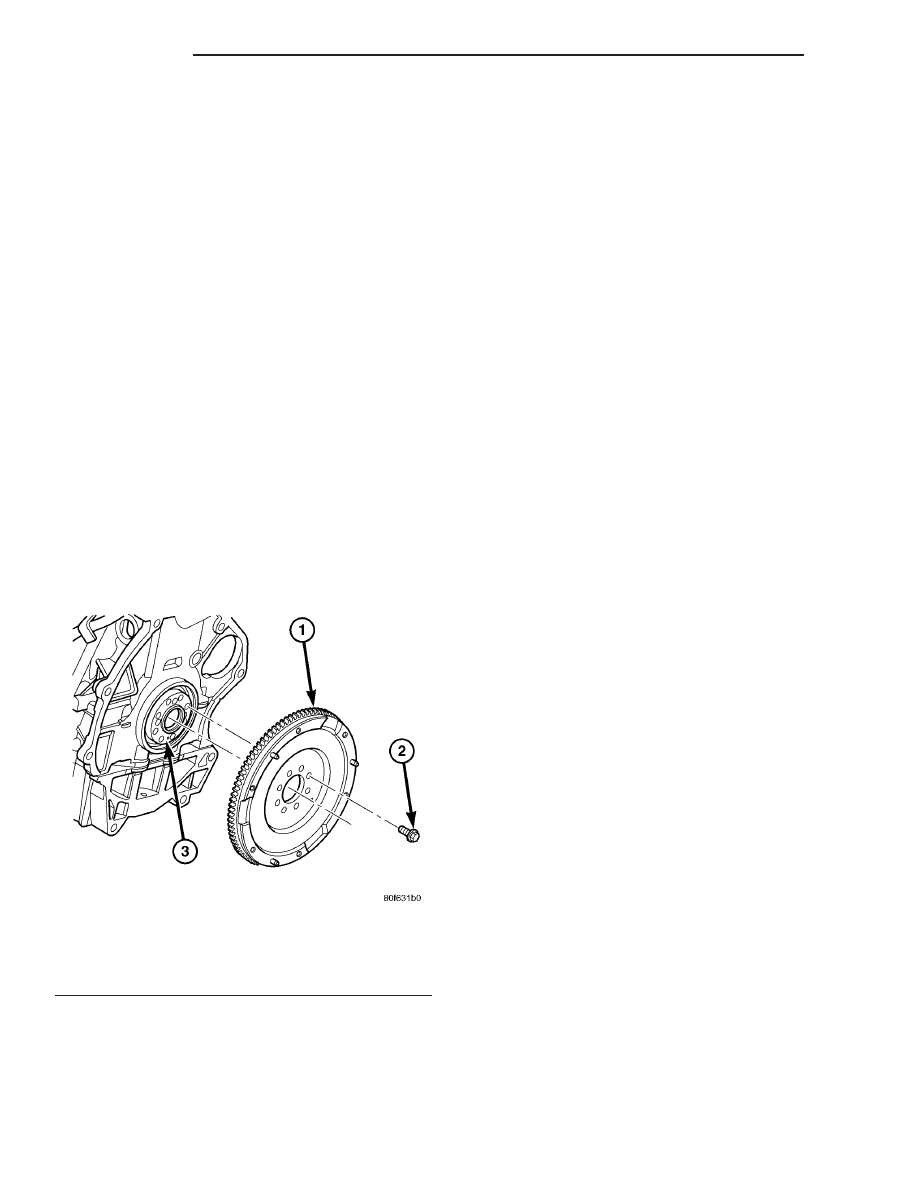
Fig. 31 Flywheel-to-Crankshaft

1 - FLYWHEEL
2 - BOLT (8)
3 - CRANKSHAFT FLANGE

6 - 20

CLUTCH

PT

CLUTCH RELEASE BEARING (Continued)

Fig. 32 Dual-Mass Flywheel (DMF)

1 - THRUST SPRING
2 - FLANGE/DIAPHRAGM SPRING

3 - PRIMARY MASS
4 - SECONDARY MASS

PT

CLUTCH

6 - 21

FLYWHEEL (Continued)

REMOVAL

(1) Remove transaxle (Refer to 21 - TRANSMIS-

SION/TRANSAXLE/MANUAL - REMOVAL).

(2) Remove clutch pressure plate and disc (Refer to

6 - CLUTCH/CLUTCH DISC - REMOVAL).

(3) Remove eight (8) flywheel-to-crankshaft bolts

and remove flywheel assembly (Fig. 33) (Fig. 34).

INSTALLATION

(1) Clean the surfaces of the flywheel and pressure

plate to make certain that all oil, grease, and rust
have been removed.

(2) 2.2L Diesel Engine Equipped Models (Fig.

33): Install flywheel to crankshaft. Install eight (8)
flywheel-to-crankshaft bolts and torque to 45 N·m (33
ft. lbs.) plus an additional

1

4

turn (90°).1.6L Engine

Equipped Models (Fig. 34): Install and torque the
flywheel-to-crankshaft bolts to 95 N·m (70 ft.lbs.).

(3) Install clutch pressure plate and disc (Refer to

6 - CLUTCH/CLUTCH DISC - INSTALLATION).

(4) Install transaxle assembly (Refer to 21 -

TRANSMISSION/TRANSAXLE/MANUAL - INSTAL-
LATION).

Fig. 33 Flywheel Bolt Pattern—2.2L Turbo Diesel

Engine

1 - FLYWHEEL ASSEMBLY

Fig. 34 Flywheel-to-Crankshaft—1.6L Engine

1 - FLYWHEEL
2 - BOLT (8)
3 - CRANKSHAFT FLANGE

6 - 22

CLUTCH

PT

FLYWHEEL (Continued)

MASTER CYLINDER - LHD

DESCRIPTION

CAUTION: The clutch master cylinder pushrod
adjustment must not be used to change pedal free-
play or pedal height. Using the adjustable pushrod
for these reasons will result in premature clutch
wear or system over/undertravel.

NOTE: The clutch master cylinder/hydraulic release
system does not have its own reservoir. This sys-
tem is supplied fluid from the brake master cylinder
reservoir.

The clutch master cylinder mounts to the dash

panel (Fig. 35) and consists of a push rod (adjustable
on LHD models), a piston and cylinder housing, an
interconnecting hydraulic tube and a supply hose
which connects to the brake master cylinder reser-
voir for fluid supply (Fig. 36).

OPERATION

The clutch master cylinder (Fig. 35) (Fig. 36) pro-

duces the hydraulic pressure necessary to disengage
the clutch. When the clutch pedal is depressed, the
push rod moves the piston to produce pressure in the
cylinder. This pressure moves fluid through the sys-
tem to the slave cylinder, which in turn operates the
release lever and bearing, disengaging the clutch.
When the clutch pedal is released, pressure is
relieved and the return spring returns the piston to
its original position until the next pedal actuation.

REMOVAL

(1) Remove air cleaner assembly (Fig. 37).

Fig. 35 Clutch Master Cylinder

1 - CLUTCH MASTER CYLINDER

Fig. 36 Clutch Hydraulic System—LHD

1 - BRAKE MASTER CYLINDER RESERVOIR
2 - CLUTCH MASTER CYLINDER
3 - ADJUSTMENT SCREW

Fig. 37 Air Cleaner Assembly Removal/Installation—

Typical

1 - AIR CLEANER ASSEMBLY

PT

CLUTCH

6 - 23


Content   ..  442  443  444  445   ..