Chrysler PT Cruiser. Manual - part 443


  Index      Chrysler     Chrysler PT Cruiser - service repair manual 2005 year


Search            


Content   ..  441  442  443  444   ..


Chrysler PT Cruiser. Manual - part 443


REMOVAL

REMOVAL - LHD

NOTE: Depending on vehicle build date, some vehi-
cles will not have the clutch pedal upstop switch
included in the switch assembly. These vehicles will
only utilize the starter inhibit (interlock) feature.

(1) Disconnect and isolate battery negative cable.
(2) Remove left lower instrument panel bezel (Fig.

22).

(3) Disconnect interlock switch and brake lamp

switch connectors.

(4) Disconnect clutch master cylinder rod from

clutch pedal pin. Inspect plastic retainer upon
removal. If retainer is damaged, it MUST be
replaced.

(5) Remove brake booster push rod retaining clip

from brake pedal. Disengage rod from pedal (Fig. 23).

(6) Remove two pedal assembly bracket to instru-

ment panel nuts (Fig. 24).

(7) Remove four brake booster/pedal bracket-to-

dash panel nuts (Fig. 24).

(8) From under the hood, pull brake master cylin-

der/booster far enough forward to obtain pedal to
bracket stud clearance.

(9) Remove the pedal bracket assembly (Fig. 24).
(10) Remove pedal pivot shaft and remove brake

and clutch pedals.

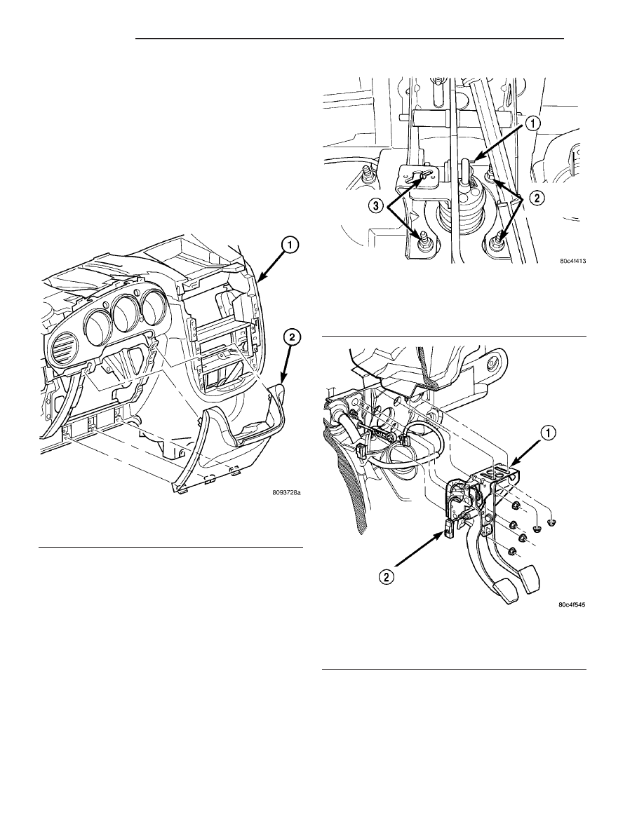
Fig. 22 Left Lower Instrument Panel Bezel

1 - INSTRUMENT PANEL
2 - INSTRUMENT PANEL STEERING COLUMN COVER

Fig. 23 Brake Booster Mounting Nuts and Rod

Retaining Clip

1 - CLIP
2 - BOOSTER MOUNTING NUTS
3 - BOOSTER MOUNTING NUTS

Fig. 24 Brake/Clutch Pedal Assembly Removal/

Installation

1 - CLUTCH/BRAKE PEDAL ASSEMBLY
2 - INTERLOCK/UPSTOP SWITCH CONNECTOR

6 - 16

CLUTCH

PT

CLUTCH INTERLOCK/UPSTOP SWITCH (Continued)

(11) Remove the interlock/upstop switch assembly

(Fig. 25) from the brake/clutch pedal bracket assem-
bly by depressing the four plastic wing tabs on each
switch.

REMOVAL - RHD

(1) Remove lower instrument panel bezel (Fig. 26).
(2) Disconnect the master cylinder push rod from

the pedal pin (Fig. 27). Inspect push rod retainer
for damage. If it is damaged (broken/cracked),
it must be replaced.

(3) Squeeze together the tangs on the switch cover

plate and slide the plate off the switch housing.

(4) Disconnect the clutch interlock/upstop switch

connector from the instrument panel wiring harness.

(5) Remove the switch from the vehicle.

INSTALLATION

INSTALLATION - LHD

NOTE: Proper switch harness routing is critical to
switch durability. Note the harness routing and
location of fasteners intended to keep wires from
contacting pedals.

(1) Install switches into the pedal bracket assem-

bly as shown in (Fig. 25). Route harness as was prior
to removal.

(2) Install

clutch

and

brake

pedals

to

pedal

bracket, and install pivot shaft and nut. Torque pivot
shaft nut to 42 N·m (31 ft. lbs.).

Fig. 25 Interlock/Upstop Switch

1 - UPSTOP SWITCH (IF EQUIPPED)
2 - INTERLOCK SWITCH
3 - CLUTCH PEDAL
4 - CONNECTOR

Fig. 26 Lower Instrument Panel Bezel—Typical

1 - INSTRUMENT PANEL
2 - INSTRUMENT PANEL STEERING COLUMN COVER

Fig. 27 Clutch Interlock/Upstop Switch

1 - INTERLOCK/UPSTOP SWITCH
2 - MASTER CYLINDER
3 - CONNECTOR

PT

CLUTCH

6 - 17

CLUTCH INTERLOCK/UPSTOP SWITCH (Continued)

(3) Install brake/clutch pedal bracket assembly

into position. Install and tighten brake booster
mounting nuts to 34 N·m (300 in. lbs.). Install and
tighten pedal bracket-to-instrument panel nuts to 34
N·m (300 in. lbs.).

(4) Install new stop lamp switch. Refer to Stop

Lamp Switch Removal and Installation.

(5) Connect brake booster rod to brake pedal.

Install retainer clip (Fig. 23).

(6) Loosen adjustment screw on clutch master cyl-

inder pushrod (Fig. 28). Gently lift clutch pedal
upwards. Raising pedal with excessive force can
damage to the pedal upstop, causing excessive
pedal travel.

NOTE: Inspect plastic retainer upon removal. If
retainer is damaged in any way (broken/cracked), it
MUST be replaced.

(7) Connect clutch master cylinder pushrod to

pedal pin and torque adjustment screw to 6 N·m (55
in. lbs.).

(8) Connect interlock/upstop and stop lamp switch

connectors.

(9) Install left lower instrument panel bezel (Fig.

22).

(10) Connect battery negative cable.
(11) Verify proper switch operation.

INSTALLATION - RHD

NOTE: Proper switch harness routing is critical to
switch durability. Note the harness routing and
location of fasteners intended to keep wires from
contacting pedals.

(1) Install the clutch interlock/upstop switch onto

the master cylinder push rod, making sure that the
push rod is oriented with the push rod retainer
toward the wiring of the switch. The master cylinder
push rod must be snapped into the clutch interlock/
upstop switch along the smaller diameter of the push
rod between the snap ring and the transition to the
larger diameter.

CAUTION: Improper assembly of the larger diameter
of the push rod into the clutch interlock/upstop
switch could cause damage to the switch or a
clutch system failure.

(2) Install the switch cover plate.

CAUTION: Inspect the plastic push rod retainer for
damage. If it is damaged (broken/cracked), it MUST
be replaced.

(3) Connect clutch master cylinder pushrod to the

clutch pedal pin.

(4) Route the wiring harness as it was prior to

removal.

(5) Secure the switch connector retaining push pin

into the appropriate hole in the pedal bracket assem-
bly.

(6) Install lower instrument panel bezel (Fig. 26).
(7) Verify proper interlock/upstop switch operation.

Fig. 28 Clutch Master Cylinder Pushrod Adjustment

Screw

1 - ADJUSTMENT SCREW

6 - 18

CLUTCH

PT

CLUTCH INTERLOCK/UPSTOP SWITCH (Continued)

CLUTCH RELEASE BEARING

DESCRIPTION

NOTE: Models equipped with the Diesel or Turbo
Engine options utilize a release bearing which is
integral to the Concentric Slave Cylinder (CSC).
(Refer to 6 - CLUTCH/SLAVE CYLINDER - DESCRIP-
TION)

1.6/2.4L Models A conventional release bearing is

used to engage and disengage the clutch pressure
plate. The clutch release bearing is mounted on the
transaxle front bearing retainer. The bearing is
attached to and operated by the release lever (Fig.
29), which moves the bearing into contact with the
clutch cover diaphragm spring.

OPERATION

The release bearing is operated by the release

lever. Slave cylinder force causes the release lever to
move the release bearing into contact with the dia-
phragm spring. As additional force is applied, the
bearing presses the diaphragm spring fingers inward
on the fulcrums. This action moves the pressure
plate rearward, relieving clamping force on the clutch
disc.

Releasing

pedal

pressure

removes

clutch

hydraulic pressure. The release bearing then moves
away from the diaphragm spring which allows the
pressure plate to exert clamping force on the clutch
disc.

REMOVAL

NOTE: Models equipped with the Diesel and Turbo
Engine option utilize a release bearing that is inte-
gral to the Concentric Slave Cylinder (CSC). (Refer
to 6 - CLUTCH/SLAVE CYLINDER - REMOVAL)

(1) Remove the transaxle from the vehicle. (Refer

to 21 - TRANSMISSION/TRANSAXLE/MANUAL -
REMOVAL)

(2) Move the lever and bearing assembly (Fig. 30)

to a vertical in-line position. Grasp the release lever
with two hands in the pivot stud socket area. Pull
with even pressure and the lever will pop off the piv-
ot–stud. Do not use a screwdriver or pry bar to pop
off the lever. This may damage the spring clip on the
lever.

(3) As a unit, remove the lever from the bearing

thrust plate. Be careful not to damage retention tabs
on bearing.

(4) Examine the condition of the bearing. It is

pre-lubricated and sealed and should not be
immersed in oil or solvent.

(5) The bearing should turn smoothly when held in

the hand under a light thrust load. A light drag
caused by the lubricant fill is normal. If the bearing
is noisy, rough, or dry, replace the complete bearing
assembly with a new bearing.

(6) Check the condition of the pivot stud spring

clips on back side of clutch release lever. If the clips
are broken or distorted, replace the clutch release
lever.

Fig. 29 Clutch Release Bearing and Lever (T350)

1 - RELEASE BEARING
2 - LEVER

Fig. 30 Release Bearing and Lever

1 - RELEASE BEARING
2 - LEVER

PT

CLUTCH

6 - 19


Content   ..  441  442  443  444   ..