Chrysler PT Cruiser. Manual - part 400


  Index      Chrysler     Chrysler PT Cruiser - service repair manual 2005 year


Search            


Content   ..  398  399  400  401   ..


Chrysler PT Cruiser. Manual - part 400


(8) Raise the transmission jack guiding the coil

springs into the spring mounting brackets on the
body of the vehicle. Raise the jack until the shock
absorber lower mounting bolts can be installed
though the axle brackets and shock absorber lower
mounting eyes (Fig. 15).

(9) Install the washer and nut on the end of each

shock absorber lower mounting bolt. Tighten the
mounting bolts to a torque of 88 N·m (65 ft. lbs.).

(10) Remove the jack.
(11) If equipped with a rear stabilizer bar, hook

the lower ends of the stabilizer bar cushion retainers
into the slots in the back of the axle, then rotate the
opposite end of the retainers upward so the mounting
bolts can be installed. Install the mounting bolt
though each cushion retainer into the threads in the
rear axle (Fig. 16). Tighten the rear stabilizer bar
cushion retainer bolts to a torque of 61 N·m (45 ft.
lbs.).

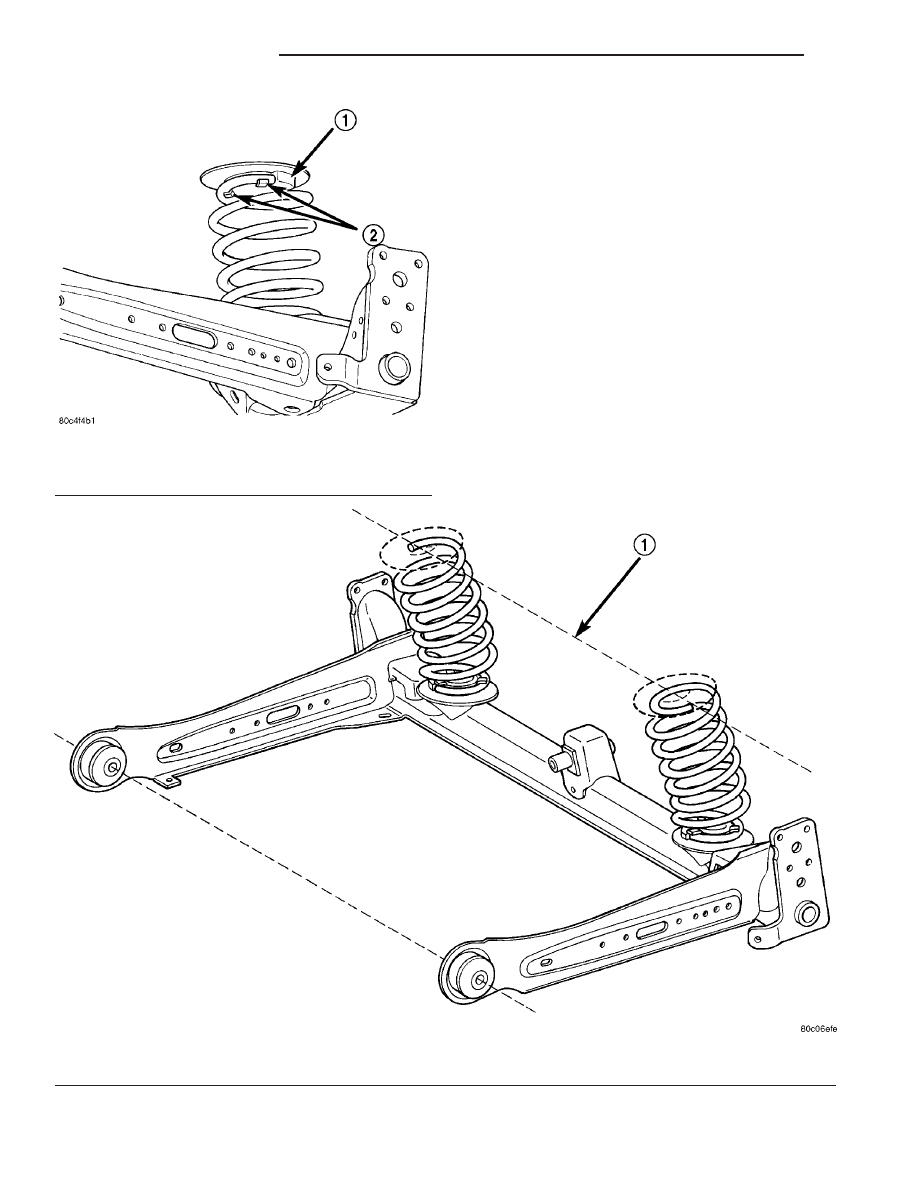
Fig. 18 Isolator Properly Installed

1 - ISOLATOR ABUTMENT
2 - FINGERS

Fig. 19 Coil Spring Orientation

1 - IMAGINARY LINE

2 - 36

REAR SUSPENSION

PT

AXLE - FRONT WHEEL DRIVE REAR (Continued)

CAUTION: When installing the watts links and bell
crank to the axle, make sure the bell crank is right-
side-up. When mounted properly, the words “BACK
UP” should be able to be read from the rear over
the top of the axle (Fig. 20).

(12) Install the bolt from the front securing the

watts link bell crank to the center of the axle (Fig.
15). Place the washer and nut on the end of the
mounting bolt and tighten it to a torque of 149 N·m
(110 ft. lbs.).

(13) On each side of the vehicle, Install the spindle

and the support plate (drum brakes) or disc brake
adapter on the end of the axle (Fig. 5).

(14) Clean the threads of the bolts used to mount

the brake shoe support plates or disc brake adapters,
and the spindles to the axle, then apply Mopar

t Stud

& Bearing Mount Adhesive or equivalent to the bolt
threads or replace with new mounting bolts.

(15) Install the four bolts securing each brake shoe

support plate or disc brake adapter, and the spindle
to the axle. Tighten the mounting bolts to a torque of
95 N·m (70 ft. lbs.).

(16) On vehicles equipped with antilock brakes,

install the wheel speed sensor heads in the disc
brake adapters or drum brake support plates and
install the bolts securing them in place (Fig. 14).
Tighten the wheel speed sensor mounting bolts to a
torque of 12 N·m (105 in. lbs.).

(17) Guide the end of each parking brake cable

through hole in the trailing arm towards the brake.

(18) Align the cable routing brackets with their

mounts on the trailing arm. Install the two bolts
securing the cable and routing brackets to the trail-
ing arm (Fig. 13). Install and tighten the mounting
bolts to a torque of 11 N·m (100 in. lbs.).

(19) On each side of the vehicle, install the park-

ing brake cable into the brake support plate or the
rear disc brake adapter. Be sure the locking fingers
on the cable retainer are expanded once the cable is
pushed all the way into the support plate or brake
adapter hole to ensure the cable is securely held in
place.

(20) On vehicles equipped with rear drum brakes,

on each side of the vehicle:

• Install the parking brake cable on the parking

brake cable actuating lever (Fig. 8).

• Install the actuating spring to the brake shoe

and the brake adjustment lever (Fig. 9).

(21) On vehicles equipped with rear disc brakes,

on each side of the vehicle:

• Install the parking brake shoe actuator lever on

the parking brake cable (Fig. 11).

• Install the parking brake shoe assemblies on the

disc brake adapter (Fig. 7).

(22) Install a hub and bearing on each rear spin-

dle. Install a NEW hub and bearing retaining nut.
Tighten the retaining nuts to a torque of 217 N·m
(160 ft. lbs.).

(23) Install the hub and bearing dust caps.

NOTE: On vehicles with rear drum brakes, before
installing the drum, it may be necessary to adjust
the rear brakes. (Refer to 5 - BRAKES/HYDRAULIC/
MECHANICAL/BRAKE

PADS/SHOES

-

ADJUST-

MENTS)

(24) On drum brake equipped vehicles, install the

brake drums.

(25) On vehicles equipped with rear disc brakes

(Fig. 6):

(a) Install the brake rotors.
(b) Install the disc brake calipers.
(c) Install the caliper guide pin bolts, then

tighten them to a torque of 22 N·m (192 in. lbs.).
(26) Install the bolts securing the disc brake flex

hoses or drum brake flex hoses to the axle trailing
arms.

(27) Install the rear tire and wheel assemblies.

Tighten all wheel nuts to a torque of 135 N·m (100 ft.
lbs.).

(28) Lower the vehicle.
(29) Install the rear parking brake cables into the

equalizer on the parking brake lever output cable
(Fig. 4).

(30) Ensure that the parking brake cables are cor-

rectly installed on the equalizer and aligned with the
cable track on the parking brake lever.

Fig. 20 Bell Crank

1 - INSTALLATION DIRECTION

PT

REAR SUSPENSION

2 - 37

AXLE - FRONT WHEEL DRIVE REAR (Continued)

WARNING: THE AUTOMATIC ADJUSTING FEATURE
OF THIS PARKING BRAKE LEVER CONTAINS A
CLOCKSPRING LOADED TO APPROXIMATELY 19
POUNDS. DO NOT RELEASE THE AUTOMATIC
ADJUSTER LOCKOUT DEVICE UNLESS THE REAR
PARKING BRAKE CABLES AND EQUALIZER ARE
CONNECTED TO THE LEVER OUTPUT CABLE.
KEEP HANDS OUT OF AUTOMATIC ADJUSTER
SECTOR AND PAWL AREA. FAILURE TO OBSERVE
CAUTION IN HANDLING THIS MECHANISM COULD
LEAD TO SERIOUS INJURY.

NOTE: The parking brake lever can only be in the
released position when releasing the automatic
adjuster.

(31) Keeping your hands clear of the automatic

adjuster sector and pawl area, firmly grasp the park-
ing brake lever pin punch (drill bit or locking pin if a
new mechanism has been installed) (Fig. 3), then
quickly remove it from the parking brake lever mech-
anism. This will allow the parking brake lever mech-
anism to automatically adjust the parking brake
cables.

(32) Cycle the parking brake lever once to position

the parking brake cables, then return the parking
brake lever its released position.

(33) Check the rear wheels of the vehicle. They

should rotate freely without excessive dragging with
the lever in its released position.

(34) Install the center console and its mounting

screws.

(35) Install the shift knob if previously removed.
(36) Apply the parking brake.
(37) Remove the blocks from the tires and wheels.
(38) Reconnect the battery negative terminal.
(39) Reinstall the air cleaner cover.
(40) Place the vehicle on an alignment rack or

drive-on hoist.

(41) With the vehicle at curb height, tighten both

trailing arm to mounting bracket pivot thru-bolts to
a torque of 122 N·m (90 ft. lbs.).

(42) Check the rear wheel alignment (Refer to 2 -

SUSPENSION/WHEEL ALIGNMENT - STANDARD
PROCEDURE). If necessary, thrust angle may be
adjusted by loosening the axle training arm bracket
bolts to the body and shifting the axle forward or
rearward, then retightening the bolts to a torque of
54 N·m (40 ft. lbs.).

AXLE PIVOT BUSHING

REMOVAL

NOTE: Before proceeding, (Refer to 2 - SUSPEN-
SION/REAR - WARNING).

(1) Raise the vehicle. (Refer to LUBRICATION &

MAINTENANCE/HOISTING - STANDARD PROCE-
DURE)

(2) Remove both rear tire and wheel assemblies

from the vehicle.

(3) Remove the bolts securing the rear brake flex

hoses (and wheel speed sensor cable on ABS models)
to the vehicle body immediately behind the axle trail-
ing arm forward brackets.

(4) Remove the two bolts on each axle trailing arm

securing the parking brake cables and routing brack-
ets to the arm (Fig. 13).

(5) Move the parking brake cables from their

mounting positions away from the bottom of the
trailing arm pivot bushing and the forward bracket.

(6) Remove the bolt securing the watts link bell

crank to the center of the axle (Fig. 15).

(7) Position a transmission jack or equivalent

under the center of the axle raising it just enough to
support the axle.

(8) Using an awl, scribe a line marking the loca-

tion of the axle trailing arm bracket, side-to-side and
front-to-rear, on the body of the vehicle (Fig. 17).

(9) Remove the bolts securing the trailing arm for-

ward brackets to the body of the vehicle.

(10) Using the lower shock mounts as a pivot

point, pry down on the forward end of the trailing
arm and place a block of wood between the top of the
arm and the body of the vehicle just to the rear of
the forward mounting bracket. Be careful not to
pinch any hoses or cables.

(11) Remove the pivot thru-bolt securing the for-

ward bracket to the trailing arm.

(12) Place Receiver, Special Tool 8405-1, on Press,

Special Tool C-4212F, and tighten the set screw (Fig.
21).

(13) Place the special tool assembly over the bush-

ing to be replaced as shown (Fig. 21). When properly
installed, the screw drive on the special tool will be
toward the center of the vehicle. Note the curve on
the axle trailing arm. This curve prevents the tool
from being properly installed in the opposite direc-
tion.

(14) Tighten the screw drive, pressing the bushing

out of the trailing arm into the receiver.

(15) Remove the tool and the bushing from the

trailing arm. Discard the used bushing.

2 - 38

REAR SUSPENSION

PT

AXLE - FRONT WHEEL DRIVE REAR (Continued)

(16) If the opposite side bushing needs to be

removed, repeat Step 11 through Step 15 on the
opposite bushing.

INSTALLATION

NOTE: To ease and attain proper installation of the
bushing using Special Tool 8405, use Mopar

T

Rub-

ber Bushing Installation Lube as indicated in the
following step.

(1) Apply Mopar

t Rubber Bushing Installation

Lube to the outside edges of the NEW bushing. Also,
lubricate the inside of the Installer, Special Tool
8405-2 with the special lube.

(2) Place the stepped end of the Installer on the

end of the trailing arm bushing sleeve that has the
curved flange at the arm (Fig. 22).

(3) Place the lubricated bushing inside the large

opening in the Installer.

(4) Place the Press, Special Tool C-4212F, with

Receiver, Special Tool 8405-1, installed, over the arm,
Installer and bushing as shown (Fig. 22). When prop-
erly installed, the screw drive on the special tool will
be toward the center of the vehicle. Note the curve on
the axle trailing arm. This curve prevents the tool
from being properly installed in the opposite direc-
tion.

(5) Tighten the screw drive, pressing the bushing

into the trailing arm sleeve. Do not over-install the
bushing; the bushing can be pushed out the other
side, into the Receiver. Push the bushing in until
freed from the installer and centered in the trailing
arm sleeve. The outer lips of the bushing must hang

out past the end of the sleeve on each side of the
trailing arm.

(6) Remove the tools from the trailing arm.
(7) If the opposite side bushing needs to be

installed, repeat Step 1 through Step 6 on the oppo-
site side.

(8) Install the trailing arm forward bracket(s) on

the axle using the following way:

(a) From above the axle, place the bracket down

over the axle trailing arm bushing aligning the
hole in the bracket with the center hole in the
bushing (Fig. 15).

(b) From the outboard side of the axle and

bracket, push the thru-bolt through the bracket
and bushing. The trailing arm bracket thru-
bolts must be installed from the outside, in
toward the center of the axle assembly, other-
wise the bolt threaded ends will come in con-
tact with the body of the vehicle upon axle
installation on vehicle.

(c) Install the nut on the inboard end of the nut.

Tighten the nut until the bracket has resistance
when turned, but still moves independent of the
axle bushing. It must be fully tightened later, once
the vehicle is at curb height.
(9) Remove the wood block between the arm and

body of the vehicle.

(10) Swing the trailing arms up aligning the

brackets with the scribed marks made upon removal
(Fig. 17), then install all eight mounting bolts (four
per side). Thread the bolts in, but do not fully
tighten.

(11) Tap the axle trailing arm brackets as neces-

sary to align the brackets to the scribed marks, then
tighten the bolts to a torque of 54 N·m (40 ft. lbs.).

(12) Remove the jack.

Fig. 21 Bushing Removal

1 - TRAILING ARM
2 - BUSHING
3 - SCREW DRIVE
4 - CURVE

Fig. 22 Bushing Installation

1 - TRAILING ARM
2 - BUSHING
3 - SCREW DRIVE
4 - CURVE

PT

REAR SUSPENSION

2 - 39

AXLE PIVOT BUSHING (Continued)


Content   ..  398  399  400  401   ..