Index Chrysler Chrysler PT Cruiser - service repair manual 2005 year
Search
Content .. 199 200 201 202 ..
Chrysler PT Cruiser. Manual - part 201
11.0
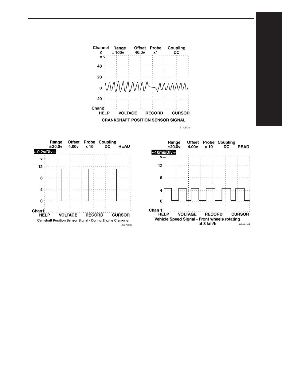
CHARTS AND GRAPHS
C
H
AR
TS
A
N
D
G
RA
P
S
285