Chrysler Pacifica. Manual - part 833


  Index      Chrysler     Chrysler Pacifica - service repair manual 2005 year


Search            


Content   ..  831  832  833  834   ..


Chrysler Pacifica. Manual - part 833


(4) Using trim tool, remove headrest sleeve(s) (Fig.

21).

INSTALLATION

(1) Place headrest sleeve(s) into position.
(2) Press down on headrest sleeve to lock into posi-

tion.

(3) Place head restraint in position (Fig. 20).
(4) Depress lock button on side of sleeve at top of

seat back.

(5) Push heat restraint down into position.

RECLINER HANDLE

REMOVAL

(1) Remove

screw

holding

recliner

handle

to

recliner spline shaft (Fig. 22).

(2) Remove recliner handle from spline shaft.

INSTALLATION

(1) Place recliner handle in position on spline

shaft.

(2) Install screw to hold recliner handle to recliner

spline shaft (Fig. 22).

SEAT ARMREST

REMOVAL

(1) Using a small flat blade, pry cap from side of

armrest (Fig. 23).

(2) Remove bolt attaching armrest to seat back.
(3) Remove armrest from seat back.

INSTALLATION

(1) Place armrest in position on seat back.

(2) Install bolt attaching armrest to seat back.

Tighten bolt to 29 N·m (21 ft. lbs.) torque.

(3) Install side cap into the side of the armrest.

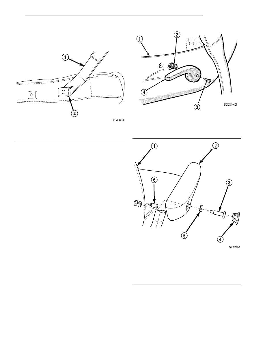
Fig. 21 REMOVING HEADREST SLEEVE

1 - TRIM TOOL
2 - HEADREST SLEEVE

Fig. 22 RECLINER HANDLE - MANUAL

1 - CUSHION SIDE COVER
2 - RECLINER SPLINE
3 - SCREW
4 - RECLINER HANDLE

Fig. 23 ARMREST

1 - SEAT BACK
2 - ARMREST
3 - SHOULDER BOLT
4 - CAP
5 - WASHER
6 - STOP SCREW

CS

SEATS

23 - 127

HEADREST (Continued)

SEAT TOWEL BAR

REMOVAL

(1) From the underside of the seat, squeeze ends of

towel bar inward to release from pivot studs (Fig.
24).

(2) Remove towel bar from seat track.

INSTALLATION

(1) Place towel bar into position under seat (Fig.

24).

(2) Squeeze ends of towel bar inward to install on

pivot studs.

SECOND ROW SEAT

REMOVAL

(1) Disconnect and isolate the battery negative

cable.

(2) Remove two nuts attaching seat to floor pan

(Fig. 25).

(3) Tilt seat forward and disconnect heated seat

wire connector (Fig. 26).

(4) Remove seat from vehicle.

Fig. 24 SEAT TOWEL BAR

1 - TOWEL BAR
2 - SEAT TRACK

Fig. 25 SECOND ROW SEATS

1 - SEAT TO FLOOR WASHER AND NUT(S)
2 - SECOND ROW BUCKET SEAT

3 - WIRE CONNECTOR
4 - WELD STUDS

23 - 128

SEATS

CS

INSTALLATION

(1) Place second row seat into position in vehicle.
(2) Connect heated seat wire connector (Fig. 26).
(3) Install two nuts attaching seat to floor pan.

Tighten nuts to 54 N·m (40 ft. lbs.) torque. (Fig. 25).

(4) Install headrest. (Refer to 23 - BODY/SEATS/

HEADREST - INSTALLATION).

(5) Connect battery negative cable.

SECOND ROW SEAT BACK
CUSHION FOAM/COVER

REMOVAL

(1) Disconnect and isolate the battery negative cable.
(2) Remove headrest and sleeves. (Refer to 23 -

BODY/SEATS/HEADREST - REMOVAL).

(3) Remove second row seat. (Refer to 23 - BODY/

SEATS/SECOND ROW SEAT - REMOVAL).

(4) Disconnect heat element wire harness.
(5) Remove armrest. (Refer to 23 - BODY/SEATS/

SEAT ARMREST - REMOVAL).

(6) Remove seat inner panel. (Refer to 23 - BODY/

SEATS/SECOND ROW SEAT INNER PANEL -
REMOVAL).

(7) Remove outboard side handle (lift on back side

of handle where it engages retainer tab and pull off).

(8) Remove two screws attaching inboard side

shield.

(9) Remove three screws attaching outboard side

shield.

(10) Disengage outer J-straps at seat back (Fig. 27).
(11) Remove screws attaching trim ring to seat

back frame (Fig. 28) and (Fig. 29).

Fig. 27 SECOND ROW SEAT BACK COVER

1 - SECOND ROW SEAT BACK COVER
2 - J-STRAPS
3 - SECOND ROW SEAT ASSEMBLY

Fig. 28 SECOND ROW SEAT BACK TRIM RING

1 - TRIM RING
2 - J-STRAPS
3 - ATTACHING SCREWS

Fig. 26 SECOND ROW DISCONNECT HEATED SEAT

WIRE CONNECTOR

1 - DISCONNECT HEATED CONNECTOR
2 - RELEASE LOCK TABS

CS

SEATS

23 - 129

SECOND ROW SEAT (Continued)

(12) Remove trim ring (Fig. 29).
(13) Disengage inner J-straps from trim ring (Fig.

30).

(14) Disconnect wiring harness (for heated seats)

at inner shield and feed back harness through hole in
shield.

(15) Remove seat back foam/cover and heating har-

ness assembly together (keep trim attached to foam
pad).

NOTE: Use care not to damage wire harness during
removal procedure.

(16) Disconnect heat seat wire harness from three

attachments and route to under side of cushion pad.

(17) Remove cushion and cover from seat back

frame (Fig. 31).

(18) Work the foam and cover under recliner

torque rod and remove seat foam/cover (Fig. 32).

(19) Separate seat cover from foam.

Fig. 29 TRIM RING FOR SEAT BACK FRAME

1 - SECOND ROW SEAT BACK FRAME
2 - TRIM RING FOR SEAT BACK FRAME
3 - SEAT BACK CUSHION

Fig. 30 SEAT BACK J-STRAPS

1 - J-STRAPS
2 - SECOND ROW SEAT BACK COVER

Fig. 31 SECOND ROW SEAT BACK FRAME AND

COVER

1 - SEAT BACK FOAM PAD
2 - SEAT BACK COVER
3 - SEAT BACK FRAME

Fig. 32 SECOND ROW SEAT BACK CUSHION AND

COVER REMOVAL

1 - SECOND ROW SEAT RECLINER TORQUE ROD
2 - SEAT BACK FOAM/COVER

23 - 130

SEATS

CS

SECOND ROW SEAT BACK CUSHION FOAM/COVER (Continued)


Content   ..  831  832  833  834   ..