Chrysler Pacifica. Manual - part 826


  Index      Chrysler     Chrysler Pacifica - service repair manual 2005 year


Search            


Content   ..  824  825  826  827   ..


Chrysler Pacifica. Manual - part 826


LIFTGATE SILL SCUFF PLATE

REMOVAL

(1) Using trim stick (C-4755), disengage push pins

attaching liftgate sill scuff plate to liftgate sill.

(2) Remove liftgate sill scuff plate from vehicle

(Fig. 22).

INSTALLATION

(1) Place sill scuff plate in position on vehicle (Fig.

22).

(2) Press sill scuff plate down to engage push pins

to liftgate sill.

QUARTER TRIM PANEL

REMOVAL

(1) Open rear door.
(2) Open liftgate.
(3) Remove rear door sill scuff plate. (Refer to 23 -

BODY/INTERIOR/REAR DOOR SILL SCUFF PLATE -
REMOVAL).

(4) Remove liftgate sill scuff plate. (Refer to 23 -

BODY/INTERIOR/LIFTGATE SILL SCUFF PLATE -
REMOVAL)

(5) Fold the first row seat back down and roll seat

forward.

(6) Fold second row seat back down.
(7) Remove rear floor storage bin. (Refer to 23 -

BODY/INTERIOR/REAR FLOOR STOWAGE BIN -
REMOVAL).

(8) Remove second row seat from vehicle to access

quarter trim panel. (Refer to 23 - BODY/SEATS/
SEAT - REMOVAL).

(9) Remove C-pillar lower seat belt anchor and

D-pillar lower seat belt anchor. (Refer to 8 - ELEC-
TRICAL/RESTRAINTS/SEAT BELT & RETRACTOR
- REMOVAL).

(10) Using a trim stick C-4755 or equivalent, dis-

engage the locking tabs and remove quarter trim
panel bolster cover (speaker grille). (Refer to 8 -
ELECTRICAL/AUDIO/SPEAKER - REMOVAL).

(11) Remove screw attaching tie down ring (Fig.

23).

(12) Using a trim stick C-4755 or equivalent, dis-

engage the locking tabs attaching quarter trim panel
body side panel.

(13) Pull quarter trim panel free enough to reach

behind trim panel to disconnect power outlet connec-
tor and speaker connector.

(14) Remove quarter trim panel from vehicle.

INSTALLATION

(1) Place quarter trim panel into position (Fig. 23).
(2) Reach behind trim panel, connect power outlet

connector and speaker connector.

(3) Set locators pins into position and pressing on

panel to engage the locking tabs attaching quarter
trim panel body side panel.

(4) Install screw attaching tie down ring.
(5) Place quarter trim panel bolster cover (speaker

grille) into position and press on bolster to engage
locking pins. (Refer to 8 - ELECTRICAL/AUDIO/
SPEAKER - INSTALLATION).

(6) Install C-pillar lower seat belt anchor and

D-pillar lower seat belt anchor. (Refer to 8 - ELEC-
TRICAL/RESTRAINTS/SEAT BELT & RETRACTOR
- INSTALLATION).

(7) Install second row seat into vehicle. (Refer to

23 - BODY/SEATS/SEAT - INSTALLATION).

(8) Install rear floor storage bin. (Refer to 23 -

BODY/INTERIOR/REAR FLOOR STOWAGE BIN -
INSTALLATION).

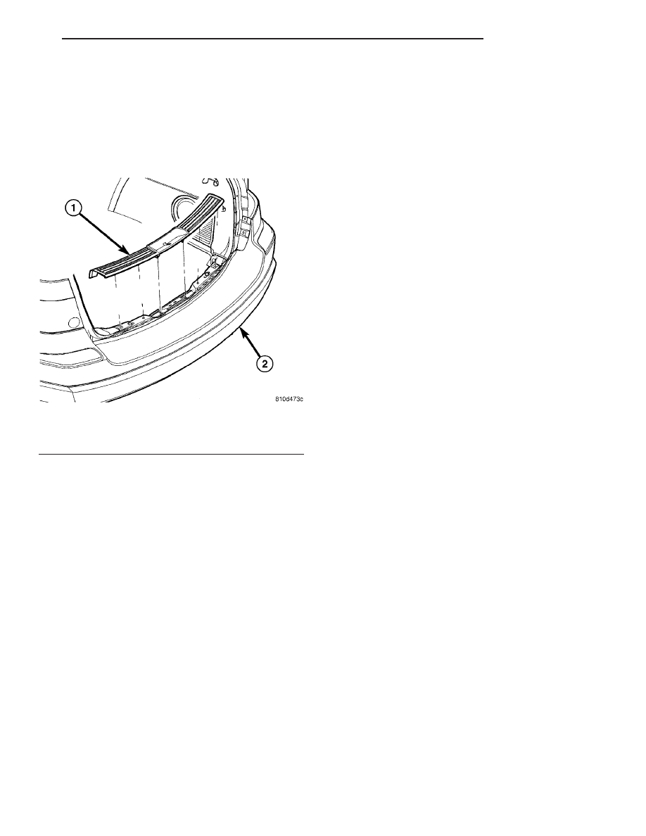
Fig. 22 LIFTGATE SILL SCUFF PANEL

1 - LIFTGATE SILL SCUFF PLATE
2 - REAR BUMPER

CS

INTERIOR

23 - 99

(9) Install liftgate sill scuff plate. (Refer to 23 -

BODY/INTERIOR/LIFTGATE SILL SCUFF PLATE -
INSTALLATION).

(10) Install rear door sill scuff plate. (Refer to 23 -

BODY/INTERIOR/REAR

DOOR

SILL

SCUFF

PLATE - INSTALLATION).

(11) Open rear door and liftgate.

REAR DOOR SCUFF PLATE

REMOVAL

(1) Using trim stick (C-4755), disengage push pins

attaching door sill plate to door sill.

(2) Remove door sill scuff plate from vehicle (Fig.

24).

INSTALLATION

(1) Place sill scuff plate in position on vehicle (Fig.

24).

(2) Place 4-way locator pin into position.
(3) Press sill scuff plate down to engage push pins

to door sill.

Fig. 23 QUARTER TRIM PANEL

1 - BODY SIDE
2 - LOCATION PINS
3 - QUARTER TRIM PANEL
4 - POWER OUTLET WIRE CONNECTOR
5 - POWER OUTLET MOUNT AND CAP

6 - POWER OUTLET BASE
7 - C-PILLAR LOWER
8 - ATTACHING SCREW
9 - GROMMET
10 - TIE DOWN RING AND SCREW

Fig. 24 REAR DOOR SILL SCUFF PLATE

1 - PUSH PINS
2 - 4-WAY LOCATION PIN
3 - REAR DOOR SILL SCUFF PLATE

23 - 100

INTERIOR

CS

QUARTER TRIM PANEL (Continued)

REAR FLOOR CONSOLE

REMOVAL

(1) Using a trim stick C-4755 or equivalent, disen-

gage the locking tabs and remove floor console scuff
plate (Fig. 25).

(2) Remove four attaching screw under scuff plate.
(3) Open cup holder and remove two attaching

screws on the bottom.

(4) Remove sidewalls attaching screws, three per

side.

(5) Remove rear floor console from vehicle.

INSTALLATION

(1) Place rear floor console into position (Fig. 25).
(2) Install sidewalls attaching screws, three per

side.

(3) Instal two attaching screws in bottom of cup

holder.

(4) Install four attaching screw under scuff plate.
(5) Place floor console scuff plate into position and

press down to engage the locking tabs.

Fig. 25 REAR FLOOR CONSOLE

1 - FRONT FLOOR CONSOLE
2 - ATTACHING SCREWS
3 - FLOOR CONSOLE SCUFF PLATE

4 - REAR FLOOR CONSOLE
5 - REAR FLOOR CONSOLE WIRE CONNECTOR
6 - FLOOR CONSOLE BASE ASSEMBLY

CS

INTERIOR

23 - 101

REAR FLOOR STOWAGE BIN

REMOVAL

(1) Open liftgate.
(2) Open rear floor storage bin lid (Fig. 26).
(3) Remove attaching screws (4) in the bottom of

bin.

(4) Remove floor storage bin from vehicle.

INSTALLATION

(1) Place floor storage bin into position (Fig. 26).
(2) Install attaching screws (4) in the bottom of

bin.

(3) Close rear floor storage bin lid.
(4) Close liftgate.

Fig. 26 FLOOR STORAGE BIN

1 - PUSH PIN
2 - WHEELHOUSE SILENCER
3 - BODY SIDE PANEL
4 - FLOOR STORAGE BIN

5 - ATTACHING SCREWS
6 - FLOOR SILENCER
7 - REAR FLOOR PANEL

23 - 102

INTERIOR

CS


Content   ..  824  825  826  827   ..