Chrysler Pacifica. Manual - part 778
 

  Index      Chrysler     Chrysler Pacifica - service repair manual 2005 year


Search            


Content   ..  776  777  778  779   ..


Chrysler Pacifica. Manual - part 778


STANDARD PROCEDURE - FLUID AND FILTER
SERVICE

NOTE: Refer to the maintenance schedules in
LUBRICATION and MAINTENANCE, or the vehicle
owner’s manual, for the recommended maintenance
(fluid/filter change) intervals for this transaxle.

NOTE: Only fluids of the type labeled Mopar

T

ATF+4

should be used. A filter change should be made at
the time of the transmission oil change. The magnet
(on the inside of the oil pan) should also be cleaned
with a clean, dry cloth.

NOTE: If the transaxle is disassembled for any rea-
son, the fluid and filter should be changed.

FLUID/FILTER SERVICE (RECOMMENDED)

(1) Raise vehicle on a hoist. Refer to LUBRICA-

TION and MAINTENANCE for proper procedures.
Place a drain container with a large opening, under
transaxle oil pan.

(2) Remove both engine mount-to-engine cross-

member cradle nuts. Using suitable screw jack and
wood block, raise engine and transmission slightly to
facilitate transaxle oil pan removal and installation.

(3) Loosen pan bolts and tap the pan at one corner

to break it loose allowing fluid to drain, then remove
the oil pan.

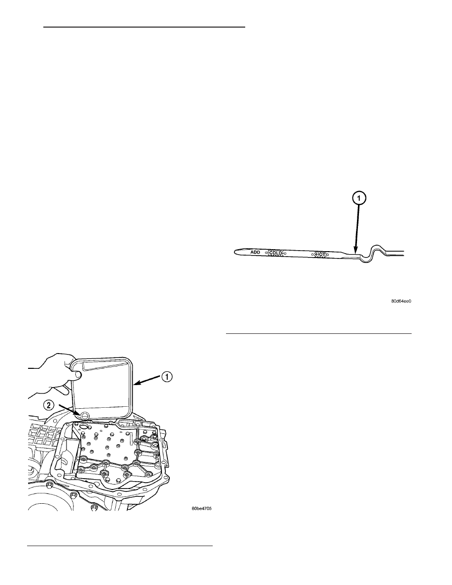
(4) Install a new filter and o-ring on bottom of the

valve body (Fig. 251).

(5) Clean the oil pan and magnet. Reinstall pan

using new Mopar Silicone Adhesive sealant. Tighten
oil pan bolts to 19 N·m (165 in. lbs.).

(6) Pour four quarts of Mopar

t ATF+4 through the

dipstick opening.

(7) Start engine and allow to idle for at least one

minute. Then, with parking and service brakes
applied, move selector lever momentarily to each
position, ending in the park or neutral position.

(8) Check the transaxle fluid level and add an

appropriate amount to bring the transaxle fluid level
to 3mm (1/8 in.) below the lowest mark on the dip-
stick (Fig. 252).

(9) Recheck the fluid level after the transaxle has

reached normal operating temperature (180°F.). Refer
to Fluid Level and Condition Check for the proper
fluid fill procedure.

(10) To prevent dirt from entering transaxle, make

certain that dipstick is fully seated into the dipstick
opening.

DIPSTICK TUBE FLUID SUCTION METHOD
(ALTERNATIVE)

(1) When performing the fluid suction method,

make sure the transaxle is at full operating temper-
ature.

(2) To perform the dipstick tube fluid suction

method, use a suitable fluid suction device (Vacula™
or equivalent).

(3) Insert the fluid suction line into the dipstick

tube.

Fig. 251 Filter and O-Ring

1 - OIL FILTER
2 - O-RING

Fig. 252 Fluid Level Indicator

1 - FLUID LEVEL INDICATOR

CS

41AE/TE AUTOMATIC TRANSAXLE

21 - 107

FLUID (Continued)

NOTE: Verify that the suction line is inserted to the
lowest point of the transaxle oil pan. This will
ensure complete evacuation of the fluid in the pan.

(4) Follow the manufacturers recommended proce-

dure and evacuate the fluid from the transaxle.

(5) Remove the suction line from the dipstick tube.
(6) Pour four quarts of Mopar

t ATF+4 through the

dipstick opening.

(7) Start engine and allow to idle for at least one

minute. Then, with parking and service brakes
applied, move selector lever momentarily to each
position, ending in the park or neutral position.

(8) Check the transaxle fluid level and add an

appropriate amount to bring the transaxle fluid level
to 3mm (1/8 in.) below the lowest mark on the dip-
stick (Fig. 252).

(9) Recheck the fluid level after the transaxle has

reached

normal

operating

temperature

(180°F.).

(Refer to 21 - TRANSMISSION/TRANSAXLE/AUTO-
MATIC - 41TE/FLUID - STANDARD PROCEDURE)

(10) To prevent dirt from entering transaxle, make

certain that dipstick is fully seated into the dipstick
opening.

GEAR SHIFT CABLE

REMOVAL

(1) Raise hood.
(2) Disconnect battery negative cable.
(3) Disconnect gearshift cable from transaxle man-

ual valve lever (Fig. 253).

(4) Remove gearshift cable housing from transaxle.

Compress retention tabs with suitable pliers and
remove from bracket.

(5) Remove front center console assembly. (Refer to

23

-

BODY/INTERIOR/FLOOR

CONSOLE

-

REMOVAL)

(6) Disconnect gearshift cable from gearshift lever

pin and mechanism base (Fig. 254). Compress reten-
tion tabs and slide cable assembly out of mechanism.

(7) Disengage cable grommet and remove cable

assembly from vehicle.

INSTALLATION

(1) Install gearshift cable to vehicle. Secure grom-

met.

(2) Install gearshift cable to shift mechanism (Fig.

255). Verfiy that retention tabs have locked cable to
mechanism.

(3) Install center console assembly. (Refer to 23 -

BODY/INTERIOR/FLOOR CONSOLE - INSTALLA-
TION)

(4) From underhood, install gearshift cable to

transaxle bracket (Fig. 256). Verify that retention
tabs are engaged to bracket.

(5) Install cable to transaxle manual valve lever

(Fig. 256).

(6) Adjust gearshift cable. (Refer to 21 - TRANS-

MISSION/TRANSAXLE/AUTOMATIC - 41TE/GEAR
SHIFT CABLE - ADJUSTMENTS)

Fig. 253 Gearshift Cable at Transaxle

1 - GEARSHIFT CABLE
2 - BRACKET
3 - MANUAL VALVE LEVER

Fig. 254 Gearshift Cable at Mechanism

1 - GEARSHIFT CABLE

21 - 108

41AE/TE AUTOMATIC TRANSAXLE

CS

FLUID (Continued)

(7) Connect battery negative cable.

ADJUSTMENTS

GEARSHIFT CABLE ADJUSTMENT

VERIFICATION

(1) Place gearshift lever in gated park (P).
(2) Attempt to move vehicle by rocking back and

forth on level ground. If vehicle does not move,
attempt to start engine. If engine starts, the park
position is correct.

(3) Set parking brake.
(4) Turn key to on/run and depress brake pedal.

Place gearshift lever in neutral (N).

(5) Attempt to start engine. If engine starts in

both neutral (N) or park (P), gearshift cable is
adjusted properly. No adjustment is required.

(6) If engine does not start in either park (P) or

neutral (N), perform adjustment procedure.

ADJUSTMENT

(1) Park the vehicle on level ground and set the

parking brake.

(2) Place the gearshift lever in gated park (P) and

remove ignition key.

(3) Loosen the cable adjustment screw at the

transaxle manual valve lever (Fig. 257).

(4) Pull the gearshift lever fully forward to the

park detent position.

(5) Release the park brake, then rock the vehicle

to assure it is in park. Reset the park brake.

(6) Tighten the cable adjustment screw to 8 N·m

(70 in. lbs.). Gearshift cable should now be properly
adjusted.

(7) Verify adjustment by using the verification pro-

cedure.

Fig. 255 Gearshift Cable at Mechanism

1 - GEARSHIFT CABLE

Fig. 256 Gearshift Cable at Transaxle

1 - GEARSHIFT CABLE
2 - BRACKET
3 - MANUAL VALVE LEVER

Fig. 257 Gearshift Cable Adjustment

1 - GEARSHIFT CABLE ADJUSTMENT SCREW
2 - GEARSHIFT CABLE

CS

41AE/TE AUTOMATIC TRANSAXLE

21 - 109

GEAR SHIFT CABLE (Continued)

HOLDING CLUTCHES

DESCRIPTION

Two hydraulically applied multi-disc clutches are

used to hold planetary geartrain components station-
ary while the input clutches drive others. The 2/4
and Low/Reverse clutches are considered holding
clutches and are contained at the rear of the trans-
axle case. (Fig. 258).

OPERATION

NOTE: Refer to the “Elements In Use” chart in Diag-
nosis and Testing for a collective view of which
clutch elements are applied at each position of the
selector lever.

2/4 CLUTCH

The 2/4 clutch is hydraulically applied in second

and fourth gears by pressurized fluid against the 2/4
clutch piston. When the 2/4 clutch is applied, the
front sun gear assembly is held or grounded to the
transaxle case.

LOW/REVERSE CLUTCH

The Low/Reverse clutch is hydraulically applied in

park, reverse, neutral, and first gears by pressurized
fluid against the Low/Reverse clutch piston. When
the Low/Reverse clutch is applied, the front planet
carrier/rear annulus assembly is held or grounded to
the transaxle case.

INPUT CLUTCH ASSEMBLY

DISASSEMBLY

(1) Mount input clutch assembly to Input Clutch

Pressure Fixture (Tool 8391).

(2) Tap down reverse clutch reaction plate to

release pressure from snap ring (Fig. 259).

(3) Remove reverse clutch snap ring (Fig. 260).
(4) Pry up and remove reverse clutch reaction

plate (Fig. 261).

(5) Remove reverse clutch pack (Fig. 262). Tag

components for assembly identification.

Fig. 258 2/4 and Low/Reverse Clutches

1 - FRONT PLANET CARRIER/REAR ANNULUS
2 - 2/4 CLUTCH
3 - L/R CLUTCH
4 - REAR PLANET CARRIER/FRONT ANNULUS
5 - REAR SUN GEAR
6 - FRONT SUN GEAR ASSEMBLY

Fig. 259 Tapping Reaction Plate

1 - #4 THRUST PLATE (SELECT)
2 - TAP DOWN REVERSE CLUTCH REACTION PLATE TO
REMOVE OR INSTALL SNAP RING
3 - INPUT SHAFT CLUTCHES RETAINER ASSEMBLY
4 - REVERSE CLUTCH REACTION PLATE

21 - 110

41AE/TE AUTOMATIC TRANSAXLE

CS


Content   ..  776  777  778  779   ..