Chrysler Pacifica. Manual - part 493
(4) If the system operation has been verified but
defogger switch LED indicator does not illuminate,
replace the A/C-heater control.
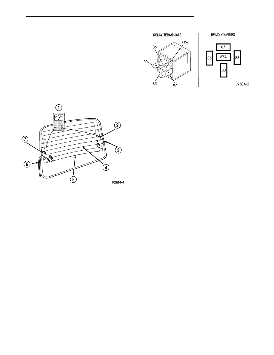
(5) If broken defogger grid lines are suspected, use
a 12-volt DC voltmeter and contact terminal B with
the negative lead and each rear glass heating grid
line at it’s mid-point with the positive lead. The volt-
meter should read approximately 6 volts at each grid
line mid-point C. If the voltmeter does not read
approximately 6 volts, repair the open grid line(s)
(Refer to 8 - ELECTRICAL/HEATED GLASS/REAR
WINDOW DEFOGGER GRID - STANDARD PROCE-
DURE).
REAR WINDOW DEFOGGER
RELAY
DESCRIPTION
The rear window defogger (EBL) relay (Fig. 4) is a
International
Standards
Organization
(ISO)-type
relay. Relays conforming to the ISO specifications
have common physical dimensions, current capaci-
ties, terminal functions and patterns. The EBL relay
is a electromechanical device that switches battery
current through a fuse in the integrated power mod-
ule (IPM) to the rear window defogger grid, the light-
emitting diode (LED) indicator of the defogger switch
and to the outside mirror heating grids (when
equipped with heated mirrors). The EBL relay is
energized when the relay coil is provided a ground
path by the control circuitry within the IPM.
The rear window defogger relay is located in the
IPM in the engine compartment.
OPERATION
The ISO-standard rear window defogger (EBL)
relay is an electromechanical switch that uses a low
current input controlled by the integrated power
module (IPM) to control the high current output to
the rear window defogger grid lines The movable,
common feed relay contact is held against the fixed,
normally closed relay contact by spring pressure.
When the electromagnetic relay coil is energized, it
draws the movable common feed relay contact away
from the fixed, normally closed relay contact and,
holds it against the fixed, normally open relay con-
tact. This action allows high current to flow to the
rear window defogger grid lines.
When the relay coil is de-energized, spring pres-
sure returns the movable relay contact back against
the fixed, normally closed contact point. The resistor
or diode is connected in parallel with the relay coil,
and helps to dissipate voltage spikes and electromag-
netic interference that can be generated as the elec-
tromagnetic field of the relay coil collapses.
The EBL relay cannot be repaired and, if faulty or
damaged, it must be replaced. Refer to the appropri-
ate wiring information for diagnosis and testing of
the ISO-standard relay and for complete rear window
defogger (EBL) wiring diagrams.
REMOVAL
(1) Disconnect and isolate the negative battery
cable.
(2) Remove the cover from the integrated power
module (IPM) (Fig. 5) located in the engine compart-
ment.
Fig. 3 Grid Line Test
1 - VOLTMETER
2 - VOLTAGE FEED (A)
3 - FEED WIRE
4 - MID-POINT (C)
5 - HEATED WINDOW GRID
6 - GROUND WIRE
7 - GROUND (B)
Fig. 4 Rear Window Defogger (EBL) Relay
30
COMMON FEED
85
COIL BATTERY
86
COIL GROUND
87
NORMALLY OPEN
87A
NORMALLY CLOSED
CS
HEATED GLASS
8G - 3
HEATED GLASS (Continued)