Chrysler Pacifica. Manual - part 432
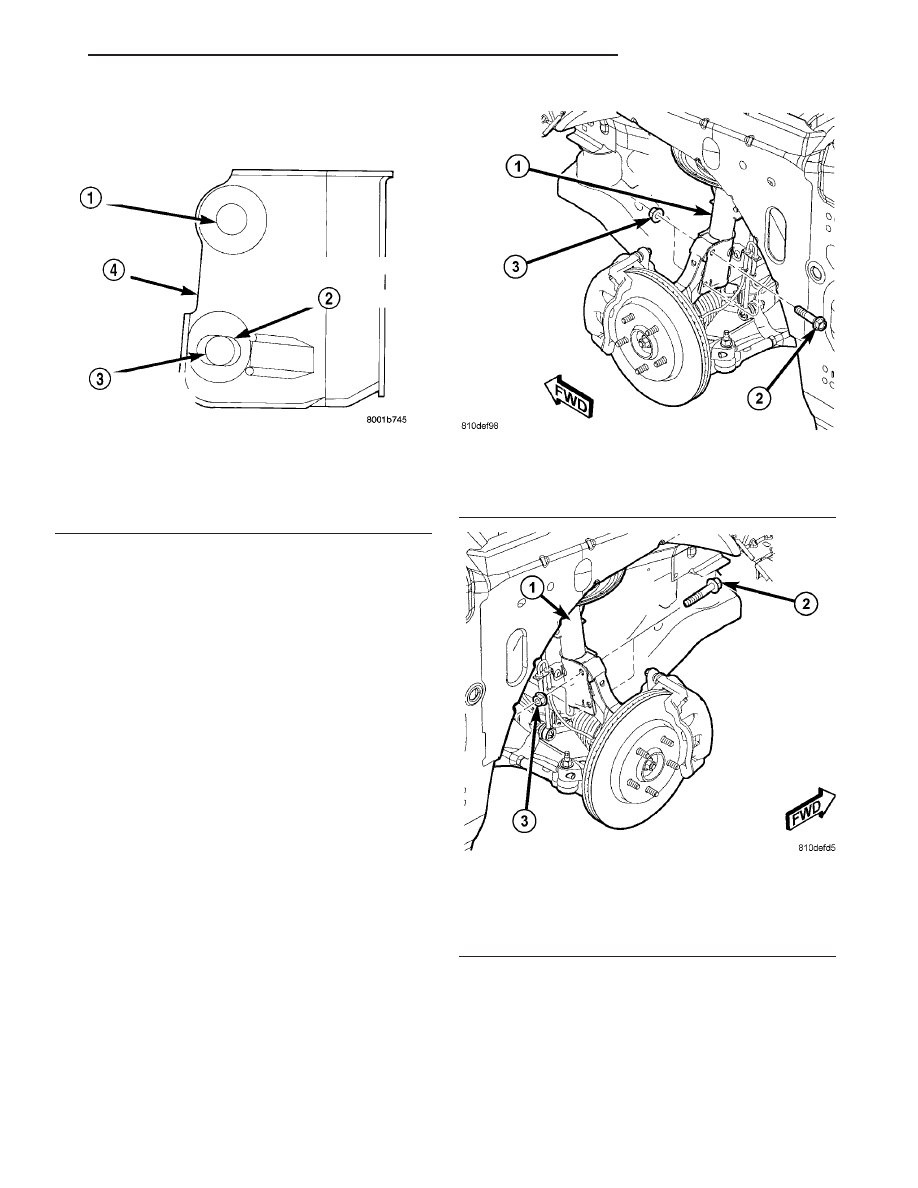
(4) Using an appropriate grinder and grinding
wheel, slot the bottom hole in both sides of the strut
clevis bracket (Fig. 8).
CAUTION: After slotting the strut clevis bracket
hole, do not install the original attaching bolts when
assembling the steering knuckle to the strut assem-
bly. Only the flange bolts, cam bolts, and dog bone
washers from the service package must be used to
attach the steering knuckle to the strut after the
mounting hole is slotted.
NOTE: The strut clevis-to-knuckle bolts are installed
differently on each side of the vehicle. Left-hand-
side bolts are installed from vehicle rear to front
(Fig. 9). Right-hand-side bolts are installed from
vehicle front to rear (Fig. 10).
(5) Position the knuckle back into the strut clevis
bracket. Using the direction indicated in the above
note, install a flanged bolt from the service package
into the upper mounting hole. Using the direction
indicated in the above note, install a cam bolt into
the bottom mounting hole (Fig. 11).
(6) Install a dog bone washer on the steering
knuckle to strut clevis bracket attaching bolts, then
install the nuts onto the bolts from the service pack-
age (Fig. 12). Tighten the bolts just enough to hold
the steering knuckle in position when adjusting cam-
ber, while still allowing the steering knuckle to move
in clevis bracket.
(7) Repeat the procedure to the other side strut
clevis bracket.
(8) Reinstall both front tire and wheel assemblies
and tighten to specifications.
(9) Lower the vehicle. Jounce the front and rear of
vehicle an equal amount of times.
(10) Adjust front camber to the preferred setting
by rotating the lower eccentric cam bolt against the
cam stop areas on the strut clevis bracket (Fig. 13).
When camber is set, tighten the upper strut clevis
bracket bolt and lower cam bolt. Again jounce front
and rear of vehicle an equal amount of times and
Fig. 8 Strut Clevis Bracket Bolt Hole Grinding Area
1 - UPPER STRUT TO STEERING KNUCKLE ATTACHING HOLE
2 - CAMBER ADJUSTMENT SLOT INDENTATION AREA ON
CLEVIS BRACKET
3 - LOWER STRUT TO STEERING KNUCKLE ATTACHING HOLE
4 - STRUT CLEVIS BRACKET
Fig. 9 Left Side Correctly Oriented Mounting Bolts
1 - STRUT
2 - BOLT
3 - NUT
Fig. 10 Right Side Correctly Oriented Mounting
Bolts
1 - STRUT
2 - BOLT
3 - NUT
CS
WHEEL ALIGNMENT
2 - 45
WHEEL ALIGNMENT (Continued)