Chrysler Pacifica. Manual - part 425
(14) Remove clamp from lower end of coil spring
and strut. Push back spring compressor upper and
lower hooks, then remove strut assembly from spring
compressor.
(15) Install strut assembly on vehicle. (Refer to 2 -
SUSPENSION/FRONT/STRUT - INSTALLATION)
INSTALLATION
CAUTION: When installing a strut assembly, make
sure strut being installed has correct coil spring for
that side of vehicle. Do not interchange two sides.
(1) Install strut assembly into strut tower, aligning
and installing three studs on upper strut mount into
holes in tower. Install three mounting nut/washer
assemblies (Fig. 28). Tighten nuts to 28 N·m (250 in.
lbs.) torque.
(2) If servicing left strut assembly, place coolant
recovery bottle in its normal mounted position and
install nuts fastening it in place. (Refer to 7 - COOL-
ING/ENGINE/COOLANT RECOVERY PRESS CON-
TAINER - INSTALLATION)
CAUTION:
Steering
knuckle
to
strut
assembly
attaching bolts are serrated and must not be turned
during installation. Install nuts while holding bolts
stationary in steering knuckle.
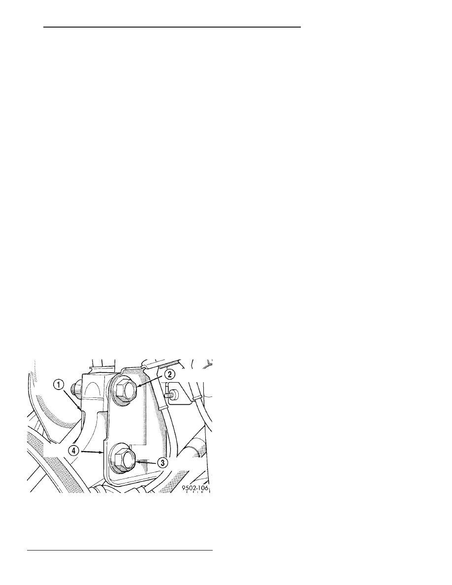
CAUTION: If strut being serviced is equipped with a
slotted lower clevis bracket mounting hole and
eccentric cam strut attaching bolt, eccentric cam
bolt must be installed in lower (slotted) hole in strut
clevis bracket (Fig. 33).
NOTE: Strut clevis-to-steering knuckle bolts are
installed differently on each side. Left hand side
bolts are to be installed from vehicle rear to front
(Fig. 26). Right side bolts are to be installed from
vehicle front to rear (Fig. 27).
(3) Align steering knuckle in clevis bracket of
strut. Install strut clevis-to-steering knuckle attach-
ing bolts (Fig. 26) (Fig. 27). Install nuts on ends of
bolts and tighten to 81 N·m (60 ft. lbs.) torque. Then,
tighten nuts an additional 1/4 (90°) turn after that
torque is met.
(4) Install
stabilizer
bar
link
mounting
stud
through rearmost hole in bracket on strut assembly.
CAUTION: When installing nut on mounting stud of
stabilizer bar link, do not allow stud to rotate in it’s
socket. Hold stud from rotating by placing an open-
end wrench on flat machined into stud (Fig. 25).
(5) Hand thread nut on end of stabilizer bar link
stud. Hold stud from turning by placing an open-end
wrench on flat machined into link’s mounting stud,
then tighten nut while holding wrench in place (Fig.
25). Tighten nut to 88 N·m (65 ft. lbs.) torque.
(6) Attach wheel speed sensor routing bracket to
strut assembly (Fig. 24). Tighten screw to 13 N·m
(115 in. lbs.) torque.
(7) Install tire and wheel assembly (Refer to 22 -
TIRES/WHEELS - INSTALLATION). Tighten wheel
mounting nuts to a torque of 135 N·m (100 ft. lbs.).
(8) Lower vehicle.
(9) Perform wheel alignment as necessary. (Refer
to 2 - SUSPENSION/WHEEL ALIGNMENT - STAN-
DARD PROCEDURE)
Fig. 33 Package Bolts Correctly Installed (Left Side
Shown)
1 - STEERING KNUCKLE
2 - FLANGED BOLT IN TOP HOLE
3 - CAM BOLT IN BOTTOM HOLE
4 - STRUT CLEVIS BRACKET
CS
FRONT SUSPENSION
2 - 17
STRUT ASSEMBLY (Continued)