Chrysler Pacifica. Manual - part 424
DIAGNOSIS AND TESTING - STRUT ASSEMBLY
(1) Inspect for a damaged or broken coil spring.
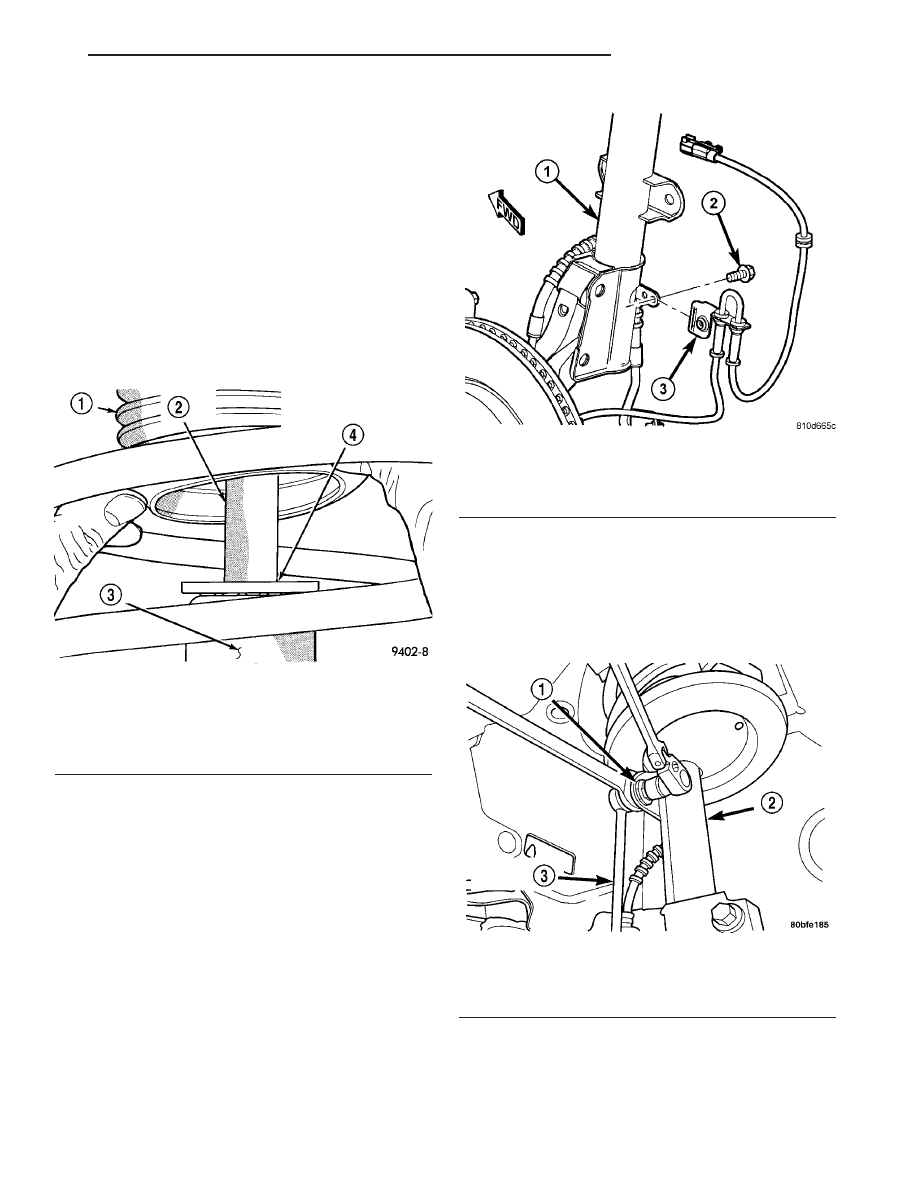
(2) Inspect for torn or damaged dust boot (Fig. 23).
(3) Inspect jounce bumper for signs of damage or
deterioration.
(4) Inspect coil spring isolator on lower spring seat
for any signs of damage or deterioration.
(5) Lift dust boot (Fig. 23) and inspect strut
(damper) for evidence of fluid running from upper
end of fluid reservoir. (Actual leakage will be a
stream of fluid running down the side and dripping
off lower end of unit). A slight amount of seepage
between the strut shaft and strut shaft seal is not
unusual and does not affect performance of the strut
assembly (Fig. 23).
REMOVAL
WARNING: DO NOT REMOVE NUT FROM STRUT
ROD WHILE STRUT ASSEMBLY IS INSTALLED IN
VEHICLE OR BEFORE STRUT ASSEMBLY SPRING
IS COMPRESSED.
(1) Raise and support vehicle. (Refer to LUBRICA-
TION & MAINTENANCE/HOISTING - STANDARD
PROCEDURE)
(2) Remove wheel and tire assembly.
(3) If both strut assemblies are to be removed,
mark strut assemblies right or left according to
which side of vehicle they were removed from.
(4) Remove screw fastening wheel speed sensor
routing bracket to strut assembly (Fig. 24).
CAUTION: When removing nut from stud of stabi-
lizer bar link, do not allow stud to rotate in it’s
socket. Hold stud from rotating by placing an open-
end wrench on flat machined into stud (Fig. 25).
(5) Remove stabilizer bar link from bracket on
strut assembly (Fig. 25). To do so, place an open-end
wrench on flat machined into link’s mounting stud,
then remove nut while holding wrench in place. Push
stud out of bracket.
CAUTION: The steering knuckle to strut assembly
attaching bolts are serrated and must not be turned
during removal. Remove nuts while holding bolts
stationary in steering knuckles.
Fig. 23 Strut Assembly Leakage Inspection (Typical)
1 - DUST BOOT
2 - STRUT SHAFT
3 - STRUT FLUID RESERVOIR
4 - INSPECT THIS AREA FOR EVIDENCE OF EXCESSIVE FLUID
LEAKAGE
Fig. 24 Wheel Speed Sensor Mounting To Strut
1 - STRUT ASSEMBLY
2 - SCREW
3 - WHEEL SPEED SENSOR ROUTING BRACKET
Fig. 25 Stabilizer Bar Link To Strut
1 - NUT
2 - STRUT
3 - STABILIZER BAR LINK
CS
FRONT SUSPENSION
2 - 13
STRUT ASSEMBLY (Continued)