Chrysler Stratus Convertible. Manual - part 273
REMOVAL AND INSTALLATION
JUNCTION BLOCK (JB)
REMOVAL
WARNING: ON VEHICLES EQUIPPED WITH AIR-
BAGS,
REFER
TO
GROUP
8M
-
PASSIVE
RESTRAINT SYSTEMS BEFORE ATTEMPTING ANY
STEERING
WHEEL,
STEERING
COLUMN,
OR
INSTRUMENT PANEL COMPONENT DIAGNOSIS OR
SERVICE. FAILURE TO TAKE THE PROPER PRE-
CAUTIONS COULD RESULT IN ACCIDENTAL AIR-
BAG DEPLOYMENT AND POSSIBLE PERSONAL
INJURY.
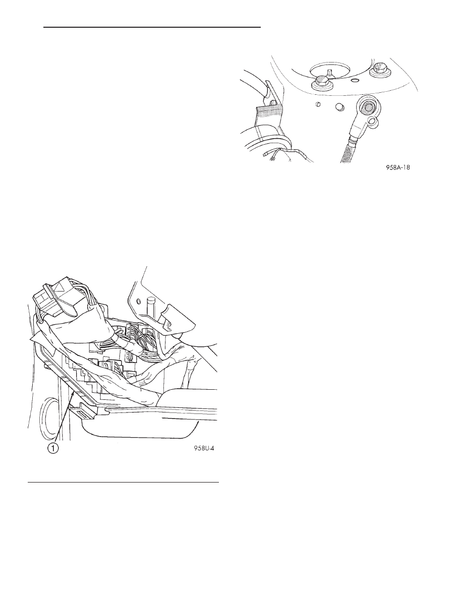
The Junction Block (JB) and Body Control Module
(BCM) are attached to each other. After removal they
can be separated. Junction Block and Body Control
Module assemblies are located on the driver’s side of
the vehicle (Fig. 3).
connectors are in good condition and connectors are
properly installed.
(1) Open hood then disconnect and isolate the bat-
tery negative remote cable from the remote terminal
on the left shock tower (Fig. 4).
(2) Open the front driver’s door and remove end
cap.
(3) Remove center bezel.
(4) Remove instrument cluster hood.
(5) Remove silencer.
(6) Remove wire harness connectors from Junction
Block.
(7) Remove Junction Block three mounting screws.
(8) Remove
Junction
Block/BCM
by
pulling
straight down from the mounting bayonet.
(9) Disconnect BCM wire connectors and remove
the assembly.
(10) Remove Junction Block/BCM from vehicle.
(11) With the Junction Block/BCM removed from
the vehicle, separate the BCM from the Junction
Block.
(12) Remove the two BCM attaching screws and
release the two BCM locking latches from the Junc-
tion Block.
(13) Disconnect BCM from the Junction Block.
INSTALLATION
For installation, reverse the above procedures.
Ensure that the wire terminals and connectors are in
good condition and connectors are properly installed
POWER DISTRIBUTION CENTER
The Power Distribution Center (PDC) is serviced
as a unit with the engine compartment wire harness.
If any internal circuit of the PDC or the PDC hous-
ing is faulty or damaged, the entire PDC and engine
compartment wire harness unit must be replaced.
REMOVAL
(1) Open hood then disconnect and isolate the bat-
tery negative remote cable from the remote terminal
on the left shock tower (Fig. 4).
(2) Remove the Air Inlet System (housing and res-
onator). Refer to Group 14, Fuel System for Removal
and Installation.
(3) Disconnect each of the engine compartment
wire harness connectors. Refer to 8W-90 - Connec-
tor Locations in Group 8W - Wiring Diagrams for
more information on the locations of the affected con-
nectors.
Fig. 3 Junction Block/BCM Location
1 – JUNCTION/BCM
Fig. 4 Battery Negative Remote Cable
JX
POWER DISTRIBUTION SYSTEMS
8O - 3