Chrysler Stratus Convertible. Manual - part 253
 

  Index      Chrysler     Chrysler Stratus Convertible - service repair manual 1995-2000 year


Search            


Content   ..  251  252  253  254   ..


Chrysler Stratus Convertible. Manual - part 253


TURN SIGNAL AND HAZARD WARNING SYSTEMS

TABLE OF CONTENTS

page

page

DESCRIPTION AND OPERATION

COMBINATION FLASHER . . . . . . . . . . . . . . . . . . . 1
EXTERIOR LAMPS . . . . . . . . . . . . . . . . . . . . . . . . 1
HAZARD WARNING SYSTEM . . . . . . . . . . . . . . . . 2
MULTI-FUNCTION SWITCH . . . . . . . . . . . . . . . . . 2

DIAGNOSIS AND TESTING

COMBINATION FLASHER . . . . . . . . . . . . . . . . . . . 3

MULTI-FUNCTION SWITCH . . . . . . . . . . . . . . . . . 5

REMOVAL AND INSTALLATION

COMBINATION FLASHER . . . . . . . . . . . . . . . . . . . 6
MULTI-FUNCTION SWITCH . . . . . . . . . . . . . . . . . 6
STEERING COLUMN SHROUDS. . . . . . . . . . . . . . 7

DESCRIPTION AND OPERATION

COMBINATION FLASHER

DESCRIPTION

The turn signal flasher and the hazard warning

flasher are combined into one unit called a combina-
tion flasher (combo-flasher).

OPERATION

An inoperative or incomplete turn signal circuit

will result in an increase in flasher speed.

The flasher is mounted to the back side of the

multi-function switch.

EXTERIOR LAMPS

DESCRIPTION

The exterior lamps are controlled by a rotary

switch located on the left stalk of the multi-function
switch on the steering column.

OPERATION

To turn lamps ON:
• Parking lamps, using left stalk turn headlamp

switch to the first detent

• Headlamps, turn switch to second detent

• Headlamp beam select, from low beam to high

beam or high to low, pull left stalk towards steering
wheel. The ignition switch must be in the RUN posi-
tion for the instrument panel high beam indicator to
light.

• Headlamp optical horn, pull left stalk towards

steering wheel, headlamps will stay ON as long as
stalk is held.

• Fog lamps, pull switch outward with headlamps

on low beam

• Panel dimmer, rotating dimmer switch regulates

intensity of the instrument panel illumination. There
are nine detents (steps) of intensity. Detent #1 is full
brightness and each detent thereafter is lower. Test-
ing the dimmer switch using the continuity test, the
resistance value is measured for each detent. Detents
#3 through #8 are measured in equal graduations, up
or down and referred to as linear. Example: if detent
#3 was #5 ohms and detent #4 was 7 ohms detent #5
should be 9 ohms.

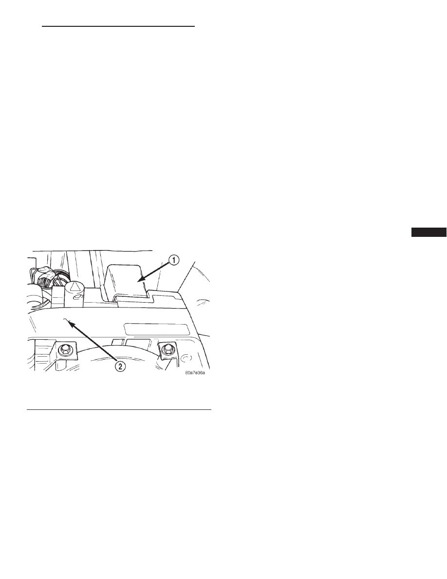
Fig. 1 Combination Flasher Location

1 – COMBINATION FLASHER
2 – MULTI-FUNCTION SWITCH

JX

TURN SIGNAL AND HAZARD WARNING SYSTEMS

8J - 1

HAZARD WARNING SYSTEM

DESCRIPTION

The hazard warning switch push button protrudes

from the top of the steering column. The hazard
warning switch push button is identified with a dou-
ble triangle, which is the international control sym-
bol for hazard warning.

OPERATION

The hazard warning system is actuated by a push

button located on the top of the steering column
between the steering wheel and the instrument
panel. The hazard switch is identified with a double
triangle on top of the button. Push and release the
button to turn the hazard function ON or OFF. The
button will move out from the steering column in the
ON position and will remain in toward the column in
the OFF position.

MULTI-FUNCTION SWITCH

WARNING: ON VEHICLES EQUIPPED WITH AIR-
BAG, SEE GROUP 8M, PASSIVE RESTRAINT SYS-
TEMS FOR AIRBAG REMOVAL PROCEDURES.

Fig. 2 Multi-Function/Exterior Lamp Switch

1 – TURN SIGNAL CONTROL STALK
2 – HAZARD WARNING BUTTON
3 – WINDSHIELD WIPER/WASHER CONTROL

4 – CANCELING ACTUATOR
5 – PANEL DIMMER SWITCH
6 – EXTERIOR LIGHTING CONTROL

Fig. 3 Hazard Warning Switch

1 – MULTI-FUNCTION SWITCH CONNECTOR
2 – HAZARD WARNING SWITCH
3 – FLASHER AND WINDSHIELD WIPER/WASHER SWITCH

CONNECTOR

4 – MOUNTING SCREWS
5 – COMBINATION FLASHER

8J - 2

TURN SIGNAL AND HAZARD WARNING SYSTEMS

JX

DESCRIPTION AND OPERATION (Continued)

DESCRIPTION

The multi-function switch contains:
• Turn signals

• Hazard warning

• Headlamps

• Headlamp beam select

• Parking lamps

• Panel dimmer

• Fog Lamp

• Headlamp optical horn

• Windshield wiper

• Pulse wipe

• Mist wipe

• Windshield washer switches.
The multi-function switch is mounted center of the

steering column. There are two levers, one on each
side of the steering column.

OPERATION

The left side controls the signaling and lighting.

The right side controls the windshield wiper and
washer system. When the driver wishes to signal his
intentions to change direction of travel, he moves the
left lever upward to cause the right signals to flash
and downward to cause the left signals to flash. After
completion of a turn the system is deactivated auto-
matically. As the steering wheel returns to the

straight ahead position the turn signals are canceled.
A canceling cam is molded to the clockspring mecha-
nism which comes in contact with the cancel actuator
on the multi-function switch. The canceling cam lobe
pushes on the cancel actuator and returns the switch
to the off position.

If only momentary signaling such as indication of a

lane change is desired, the switch is actuated to a
left or right intermediate detent position. In this
position the signal lamps flash as described above,
but the switch returns to the OFF position as soon as
the lever is released.

When the system is activated, one of two indicator

lamps mounted in the instrument cluster flashes in
unison with the turn signal lamps, indicating to the
driver that the system is operating. The windshield
wiper and wash system is covered in Group 8K,
Windshield Wipers and Washers.

DIAGNOSIS AND TESTING

COMBINATION FLASHER

For combination flasher Diagnosis and Testing,

refer to the Combination Flasher Diagnosis table.

Fig. 4 Multi-Function Switch

1 – TURN SIGNAL CONTROL STALK
2 – HAZARD WARNING BUTTON
3 – WINDSHIELD WIPER/WASHER CONTROL

4 – CANCELING ACTUATOR
5 – PANEL DIMMER SWITCH
6 – EXTERIOR LIGHTING CONTROL

JX

TURN SIGNAL AND HAZARD WARNING SYSTEMS

8J - 3

DESCRIPTION AND OPERATION (Continued)

COMBINATION FLASHER DIAGNOSIS

CONDITION

POSSIBLE CAUSES

CORRECTION

SYSTEM DOES NOT FLASH
ON ONE SIDE, INDICATOR
LAMP FLASHES AT
DOUBLE NORMAL RATE.

1) FAULTY EXTERNAL LAMP.
2) POOR GROUND AT LAMP.
3) OPEN CIRCUIT IN WIRING
TO EXTERNAL LAMP.
4) FAULTY CONTACT ON
SWITCH.

1) REPLACE LAMP.
2) CHECK AND/OR REPLACE WIRING.
3) REPLACE WIRING HARNESS. CHECK
CONNECTORS.
4) REPLACE MULTIFUNCTION SWITCH.

INDICATOR LAMP FLASHES
AT DOUBLE THE NORNAL
RATE. EXTERNAL LAMP-
DIM AND FLASHES
RAPIDLY OR NO FLASH

1) LOOSE OR CORRODED
EXTERNAL LAMP
CONNECTION.
2) POOR GROUND CIRCUIT
OR EXTERNAL LAMP.

1) REPLACE SOCKET/HARNESS.
2) REPLACE WIRING/HARNESS. CHECK
CONNECTORS.

HAZARD WARNING
MALFUNCTION/SYSTEM
DOES NOT FLASH

1) FAULTY FUSE.
2) FAULTY FLASHER.
3) OPEN CIRCUIT IN FEED
WIRE TO SWITCH.
4) FAULTY CONTACT IN
SWITCH.
5) OPEN OR GROUNDED
CIRCUIT IN WIRING TO
EXTERNAL LAMPS.

1) REPLACE FUSE.
2) REPLACE FLASHER.
3) REPLACE WIRING/HARNESS. CHECK
CONNECTORS.
4) REPLACE MULTIFUNCTION SWITCH.
5) REPLACE WIRING/HARNESS.

INDICATOR LAMP FLASHES
AT DOUBLE NORMAL RATE,
EXTERNAL LAMP DOES
NOT LIGHT

1) OPEN CIRCUIT IN WIRE TO
EXTERNAL LAMP.
2) BURNED OUT LAMP.

1) REPLACE WIRING/HARNESS.
2) REPLACE LAMP.

SYSTEM DOES NOT FLASH
ON EITHER SIDE

1) FAULTY FUSE.
2) FAULTY FLASHER UNIT.
3) LOOSE BULKHEAD
CONNECTOR.
4) LOOSE OR FAULTY REAR
WIRING/HARNESS OR
TERMINALS.
5) OPEN CIRCUIT TO
FLASHER UNIT.
6) OPEN CIRCUIT IN FEED
WIRE TO TURN SIGNAL
SWITCH.
7) FAULTY SWITCH
CONNECTION.
8) OPEN OR GROUNDED
CIRCUIT IN WIRING TO
EXTERNAL LAMPS.
9) BURNED OUT LAMPS.

1) REPLACE FUSE.
2) REPLACE FLASHER.
3) TIGHTEN CONNECTOR.
4) REPLACE WIRING/HARNESS.
5) CHECK CONNECTORS, REPLACE
WIRING/HARNESS.
6) CHECK CONNECTORS, REPLACE
WIRING/HARNESS.
7) REPLACE SWITCH.
8) REPLACE WIRING/HARNESS.
9) REPLACE LAMPS.

SYSTEM DOES NOT
CANCEL AFTER
COMPLETION OF TURN

1) BROKEN CANCELLING
FINGER ON SWITCH.
2) BROKEN OR MISSING
CANCELLING CAM ON
CLOCKSPRING.
3) STICKING CANCELLING
FINGER ON MULTIFUNCTION
SWITCH.

1) REPLACE MULTIFUNCTION SWITCH.
2) REPLACE CLOCKSPRING.
3) REPLACE MULTIFUNCTION SWITCH.

8J - 4

TURN SIGNAL AND HAZARD WARNING SYSTEMS

JX

DIAGNOSIS AND TESTING (Continued)


Content   ..  251  252  253  254   ..