Chrysler Stratus Convertible. Manual - part 185
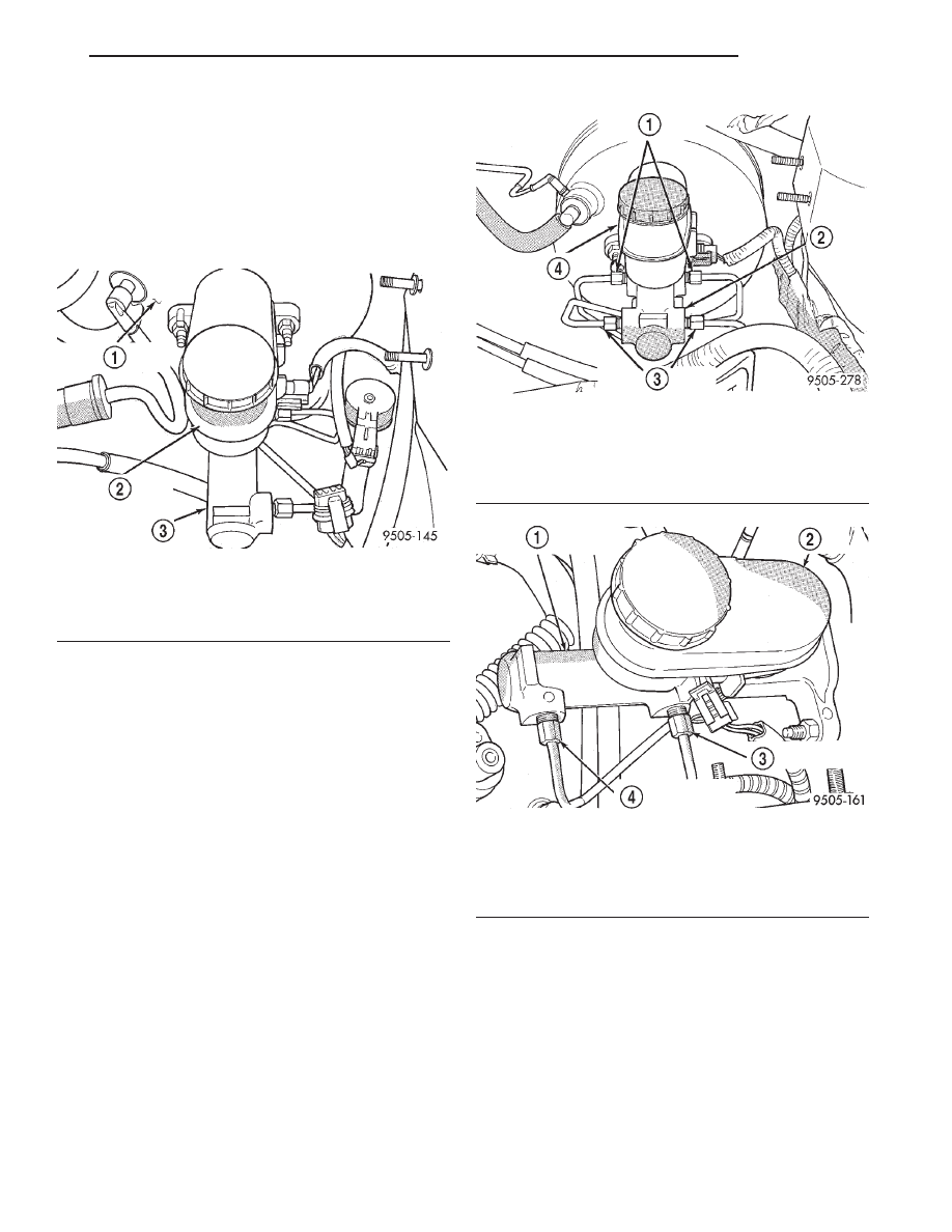
The master cylinder assembly (Fig. 2) consists of
the following components. The body of the master
cylinder is an anodized aluminum casting. It has a
machined bore to accept the master cylinder piston
and threaded ports with seats for hydraulic brake
line connections. The brake fluid reservoir of the
master cylinder assembly is made of a see through
plastic.
OPERATION
When the brake pedal in depressed, the master cyl-
inder primary and secondary pistons apply brake
pressure through the chassis brake tubes and propor-
tioning valves to each brake assembly.
On Non-ABS master cylinders, the primary outlet
ports (Fig. 3) supply hydraulic pressure to the right
front and left rear brakes. The secondary outlet ports
(Fig. 3) supply hydraulic pressure to the left front
and right rear brakes.
On ABS master cylinders, the primary outlet port
(Fig. 4) supplies hydraulic pressure to the right front
and left rear brakes. The secondary outlet port (Fig.
4) supplies hydraulic pressure to the left front and
right rear brakes.
Fig. 2 Master Cylinder
1 – POWER BRAKE VACUUM BOOSTER
2 – MASTER CYLINDER FLUID RESERVOIR
3 – MASTER CYLINDER BODY
Fig. 3 Primary And Secondary Ports Without ABS
1 – MASTER CYLINDER PRIMARY PORTS
2 – MASTER CYLINDER
3 – MASTER CYLINDER SECONDARY PORTS
4 – MASTER CYLINDER FLUID RESERVOIR
Fig. 4 Primary And Secondary Ports With ABS
1 – MASTER CYLINDER ASSEMBLY
2 – BRAKE FLUID RESERVOIR
3 – MASTER CYLINDER PRIMARY PORT
4 – MASTER CYLINDER SECONDARY PORT
JX
BRAKES
5 - 3
DESCRIPTION AND OPERATION (Continued)