Chrysler Stratus Convertible. Manual - part 126
 

  Index      Chrysler     Chrysler Stratus Convertible - service repair manual 1995-2000 year


Search            


Content   ..  124  125  126  127   ..


Chrysler Stratus Convertible. Manual - part 126


• Panel repair for both flexible and rigid panels

are basically the same. The primary difference
between flexible panel repair and rigid panel repair
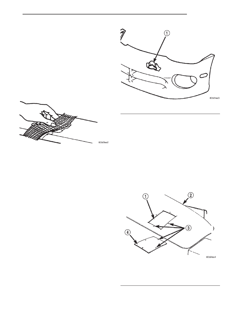
is in the adhesive materials used (Fig. 6).

• The technician should first decide what needs to

be done when working on any type of body panel.
One should determine if it is possible to return the
damage part to its original strength and appearance
without exceeding the value of the replacement part.

• When plastic repairs are required, it is recom-

mended that the part be left on the vehicle when
every possible. That will save time, and the panel
will remain stationary during the repair. Misalign-
ment can cause stress in the repair areas and can
result in future failure.

VISUAL INSPECTION

Sheet Molded Compound (SMC) and Resin Transfer

Molded (RTM), because they are composites, react dif-
ferently to impact that sheet metal does. Composite
materials can mask the severity of an accident. Adhe-
sive bond lines, interior structure of the doors, and
steel structure need to be inspected carefully to get a
true damage assessment. Close inspection may require
partial removal of interior trim or inner panels.

Identify the type of repair:
Puncture or Crack – Damage that has penetrated

completely through the panel. Damage is confined to
one general area; a panel section is not required. How-
ever, a backer panel, open fiberglass tape, or matted
material must be bonded from behind (Fig. 7).

PANEL SURFACE PREPARATION

If a body panel has been punctured, cracked, or

crushed, the damaged area must be removed from
the panel to achieve a successful repair. All spider
web cracks leading away from a damaged area must
be stopped or removed. To stop a running crack in a
SMC or RTM panel, drill a 6 mm (0.250 in.) hole at
the end of the crack farthest away from the damage.
If spider web cracks can not be stopped, the panel
would require replacement. The surfaces around the
damaged area should be stripped of paint and freed
from was and oil. Scuff surfaces around repair area

with 360 grit wet/dry sand paper, or equivalent, to
assure adhesion of epoxy repair materials.

PATCHING PANELS

An RTM or SMC panel that has extensive punc-

ture type damage can be repaired by cutting out the
damaged material (Fig. 8). Use a suitable reciprocat-
ing saw or cut off wheel to remove the section of the
SMC or RTM panel that is damaged. The piece cut
out can be used as a template to shape the new
patch. It is not necessary to have access to the back
of the panel to install a patch. Bevel edges of cutout
at 20 degrees to expose a larger bonding area on the
outer side. This will allow for an increased reinforce-
ment areas.

Fig. 6 Fiberglass Tape

Fig. 7 Damage Component

1 – PUNCTURE

Fig. 8 Damaged Panel Cutout and Patch

1 – CUTOUT
2 – DAMAGED BODY PANEL
3 – 4MM (0.160 IN.) HOLES
4 – PATCH CUT TO SIZE

JX

BODY

23 - 37

SERVICE PROCEDURES (Continued)

PANEL PATCH FABRICATIONS

A patch can be fabricated from any rigid fiberglass

panel that has comparable contour with the repair
area. discard SMC or RTM panels. Lift gates and
fenders can be used to supply patch material. If
existing material is not available or compatible, a
patch can be constructed with epoxy and reinforce-
ment mesh (dry wall tape). Perform the following
operation if required:

(1) Cover waxed paper or plastic with adhesive

backed nylon mesh (dry wall tape) larger than the
patch required (Fig. 9).

(2) Tape waxed paper or plastic sheet with mesh to

a surface that has a compatible contour to the repair
area.

(3) Apply a liberal coat of epoxy adhesive over the

reinforcement mesh (Fig. 9). If necessary apply a sec-
ond or third coat of epoxy and mesh after firs coat
has cured. The thickness of the patch should be the
same as the repair area.

(4) After patch has cured, peel waxed paper or

plastic from the back of the patch.

(5) If desired, a thin film coat of poesy can be

applied to the back of the patch to cover mesh for
added strength.

PANEL PATCH INSTALLATION

(1) Make a paper or cardboard pattern the size

and shape of the cutout hole in the panel.

(2) Trim 3 mm (0.125 in.) from edges of pattern so

patch will have a gap between connecting surfaces.

(3) Using the pattern as a guide, cut the patch to

size.

(4) Cut scrap pieces of patch material into 50 mm

(2 in.) squares to use as patch supports to sustain
the patch in the cutout.

(5) Drill 4 mm (0.160 in.) holes 13 mm (0.5 in.) in

from edge of cutout hole (Fig. 8).

(6) Drill 3 mm (0.125 in.) holes in the support

squares 13 mm (0.5 in.) from the edge in the center
of one side.

(7) Scuff the backside of the body panel around the

cutout hole with a scuff pad or sandpaper.

(8) Mix enough epoxy to cover one side of all sup-

port squares.

(9) Apply epoxy to the support squares on the half

with the hole pre-drilled in it.

(10) Using number 8 sheet metal screws, secure-

support squares to back side of body panel with
epoxy sandwiched between the panel and squares
(Fig. 10).

Fig. 10 Secure Support Squares To Body Panel

1 – SUPPORT SQUARES
2 – SCREWS
3 – DAMAGED BODY PANEL

Fig. 9 Fabricated Panel

1 – STRUCTURAL ADHESIVE OR EPOXY RESIN
2 – FIBERGLASS CLOTH OR FIBERGLASS MESH TAPE
3 – WIDTH OF V-GROOVE
4 – WAXED PAPER

23 - 38

BODY

JX

SERVICE PROCEDURES (Continued)

(11) Position

patch

in

cutout

against

support

squares and adjust patch until the gap is equal alon-
gall sides (Fig. 11).

(12) Drill 3 mm (0.125 in.) holes in the support

squares through the pre-drilled holes in the patch.

(13) Apply a coat of epoxy to the exposed ends of

the support squares (Fig. 12).

(14) Install screws to hold the patch to support

squares (Fig. 13). Tighten screws until patch surface
is flush with panel surface.

(15) Allow epoxy to cure, and remove all screws.
(16) Using a 125 mm (5 in.) 24 grit disc grinder,

grind a 50 mm (2 in.) to 75 mm (3 in.) wide and 2
mm (0.080 in.) deep path across the gaps around the
patch (Fig. 14). With compressed air, blow dust from
around patch.

(17) Apply adhesive backed nylon mesh (dry wall

tape) over gaps around patch (Fig. 15).

(18) Mix enough epoxy to cover the entire patch area.
(19) Apply epoxy over the mesh around patch, and

smooth epoxy with a wide spreader to reduce finish
grinding. Use two to three layers of mesh and epoxy
to create a stronger repair (Fig. 16).

Fig. 11 Position Patch In Cutout And Align

1 – CUTOUT
2 – SUPPORT SQUARES

Fig. 12 Apply Epoxy To Support Squares

1 – APPLICATOR
2 – SUPPORT SQUARES
3 – EPOXY

Fig. 13 Install Screws

1 – PATCH
2 – GAP

JX

BODY

23 - 39

SERVICE PROCEDURES (Continued)

PATCHED PANEL SURFACING

After patch panel is installed, the patch area can

be finished using the same methods as finishing
other types of body panels. If mesh material is
exposed in the patched area, grind surface down, and
apply a coat of high quality rigid plastic body filler.
Prime, block sand, and paint as required.

Fig. 14 Grind Surface

1 – PATCH
2 – GAP
3 – DISC GRINDER

Fig. 15 Cover Gaps With Mesh

1 – GROUND DOWN AREA
2 – PATCH
3 – MESH

Fig. 16 Cover Mesh With Epoxy

1 – EPOXY
2 – MESH
3 – PATCH
4 – SPREADER

23 - 40

BODY

JX

SERVICE PROCEDURES (Continued)


Content   ..  124  125  126  127   ..