Chrysler Stratus Convertible. Manual - part 115
 

  Index      Chrysler     Chrysler Stratus Convertible - service repair manual 1995-2000 year


Search            


Content   ..  113  114  115  116   ..


Chrysler Stratus Convertible. Manual - part 115


SERVICE PROCEDURES

TIRE INFLATION PRESSURES

WARNING: OVER

OR

UNDER

INFLATED

TIRES

CAN AFFECT VEHICLE HANDLING. THE TIRE CAN
FAIL SUDDENLY, RESULTING IN LOSS OF VEHICLE
CONTROL.

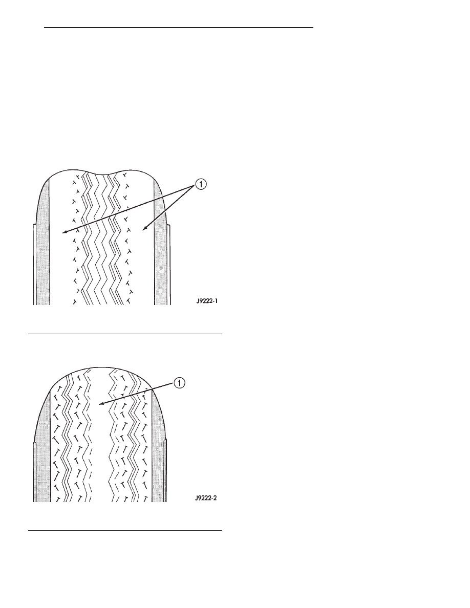
Under inflation causes rapid shoulder wear of the

tire tread and tire flexing. This can result in failure
of the tire. (Fig. 4).

Over inflation causes rapid center wear and loss of

the tire’s ability to cushion shocks (Fig. 5).

Improper inflation can cause:
• Uneven wear patterns

• Reduced tread life

• Reduced fuel economy

• Unsatisfactory ride

• The vehicle to drift.
Proper tire air inflation pressure specifications can

be found on the Vehicle Tire Placard provided with
the vehicle. See owner’s manual.

Tire pressures have been chosen to provide safe

operation, vehicle stability, and a smooth ride. Tire
pressure should be checked cold once per month.
Check tire pressure more frequently when the
weather temperature varies widely. Tire pressure will
decrease when the outdoor temperature drops.

Tire inflation pressures specified on the placard

are always cold inflation pressure. Cold inflation
pressure is obtained after the vehicle has not been
operated for at least 3 hours, or the vehicle is driven
less than one mile after being inoperative for 3
hours. Tire inflation pressures may increase from 2
to 6 pounds per square inch (psi) during operation.
Do not reduce this normal pressure build-up.

TIRE PRESSURE FOR HIGH SPEED
OPERATION

DESCRIPTION

Where speed limits allow the vehicle to be driven

at high speeds, correct tire inflation pressure is very
important. For speeds up to and including 120 km/h
(75 mph), tires must be inflated to the pressures
shown on the tire placard. For continuous speeds in
excess of 120 km/h (75 mph), tires must be inflated
to the maximum pressure specified on the tire side-
wall.

Vehicles loaded to the maximum capacity should

not be driven at continuous speeds above 75 mph
(120 km/h).

For emergency vehicles that are driven at speeds

over 90 mph (144 km/h), special high speed tires
must be used. Consult tire manufacturer for correct
inflation pressure recommendations.

TIRE AND WHEEL ROTATION

NON-DIRECTIONAL TREAD PATTERN TIRES

Tires on the front and rear axles operate at differ-

ent loads and perform different functions. For these
reasons, they wear at unequal rates, and tend to
develop irregular wear patterns. These effects can be
reduced by timely rotation of tires. The benefits of
rotation are especially worthwhile. Rotation will
increase tread life, help to maintain mud, snow, and
wet traction levels, and contribute to a smooth, quiet
ride.

Fig. 4 Under Inflation Wear

1 – THIN TIRE TREAD AREAS

Fig. 5 Over Inflation Wear

1 – THIN TIRE TREAD AREA

JX

TIRES AND WHEELS

22 - 5

The suggested rotation method is the forward-cross

tire rotation method (Fig. 6). This method takes
advantage of current tire industry practice which
allows rotation of radial-ply tires. Other rotation
methods may be used, but may not have all the ben-
efits of the recommended method.

NOTE: Only the 4 tire rotation method may be used
if the vehicle is equipped with a low mileage or tem-
porary spare tire.

DIRECTIONAL TREAD PATTERN TIRES

Some vehicles are fitted with special high-perfor-

mance tires having a directional tread pattern. These
tires are designed to improve traction on wet pave-
ment. To obtain the full benefits of this design, the
tires must be installed so that they rotate in the cor-
rect direction. This is indicated by arrows on the tire
sidewalls.

When wheels and tires are being installed, extra

care is needed to ensure that this direction of rota-
tion is maintained.

Refer to Owner’s Manual for rotation schedule.

REPAIRING TIRE LEAKS

For proper repairing, a radial tire must be removed

from the wheel. Before dismounting the tire from the
wheel, a reference mark should be placed on the tire
at the valve stem location. This reference mark will
ensure that the tire is remounted back on the wheel
in its original position. Repairs should only be made
if the defect, or puncture, is in the tread area (Fig.
7). The tire should be replaced if the puncture is
located in the sidewall.

Deflate tire completely before dismounting tire

from the wheel. Use lubrication such as a mild soap
solution when dismounting or mounting tire. Use
tools free of burrs or sharp edges which could dam-
age the tire or wheel rim.

Before mounting tire on wheel, make sure all rust

is removed from the rim bead and repaint if neces-
sary.

Install wheel on vehicle, and progressively tighten

all 5 wheel nuts to a torque of 135 N·m (100 ft. lbs.).

TIRE AND WHEEL MATCH MOUNTING

Wheels and tires are match mounted at the factory.

This means that the high spot of the tire is matched
to the low spot on the wheel rim. This technique is
used to reduce run-out in the wheel/tire assembly.
The high spot on the tire is marked with a paint
mark or a bright colored adhesive label on the out-
board sidewall. The low spot on the rim is identified
with a label on the outside of the rim and a dot or
line in the drop well on the tire side of the rim. If the
outside label has been removed the tire will have to
be removed to locate the dot or line on the inside of
the rim.

Before dismounting a tire from its wheel, a refer-

ence mark should be placed on the tire at the valve
stem location. This reference will ensure that it is
remounted in the original position on the wheel.

(1) Measure the total indicator runout on the cen-

ter of the tire tread rib. Record the indicator reading.
Mark the tire to indicate the high spot. Place a mark
on the tire at the valve stem location (Fig. 8).

(2) Break down the tire and remount it 180

degrees on the rim (Fig. 9).

Fig. 6 Forward-Cross Tire Rotation Method

Fig. 7 Tire Repair Area

1 – REPAIRABLE AREA

22 - 6

TIRES AND WHEELS

JX

SERVICE PROCEDURES (Continued)

(3) Measure the total indicator runout again. Mark

the tire to indicate the high spot.

(4) If runout is still excessive (in excess of 1.524

mm or 0.060 in.), the following procedures must be
done.

• If the high spot is within 102 mm (4.0 in.) of the

first spot and is still excessive, replace the tire.

• If the high spot is within 102 mm (4.0 in.) of the

first spot on the wheel, the wheel may be out of spec-
ifications. Refer to Wheel and Tire Runout.

• If the high spot is NOT within 102 mm (4.0 in.)

of either high spot, draw an arrow on the tread from
second high spot to first. Break down the tire and
remount it 90 degrees on rim in that direction (Fig.
10). This procedure will normally reduce the runout
to an acceptable amount.

CLEANING AND INSPECTION

CLEANING TIRES

Remove the protective coating on the tires before

delivery of a vehicle. This coating may cause deteri-
oration of the tires.

To remove the protective coating, apply warm

water and let it soak for a few minutes. Afterwards,
scrub the coating away with a soft bristle brush.
Steam cleaning may also be used to remove the coat-
ing.

NOTE: DO NOT use gasoline, mineral oil, oil-based
solvent or a wire brush for cleaning.

Fig. 8 First Measurement On Tire

1 – REFERENCE MARK
2 – 1ST MEASUREMENT HIGH SPOT MARK TIRE AND RIM
3 – WHEEL
4 – VALVE STEM

Fig. 9 Remount Tire 180 Degrees

1 – VALVE STEM
2 – REFERENCE MARK

Fig. 10 Remount Tire 90 Degrees In Direction of

Arrow

1 – 2ND HIGH SPOT ON TIRE
2 – 1ST HIGH SPOT ON TIRE

JX

TIRES AND WHEELS

22 - 7

SERVICE PROCEDURES (Continued)

WHEELS

TABLE OF CONTENTS

page

page

DESCRIPTION AND OPERATION

WHEEL . . . . . . . . . . . . . . . . . . . . . . . . . . . . . . . . . 8

DIAGNOSIS AND TESTING

WHEEL INSPECTION. . . . . . . . . . . . . . . . . . . . . . . 9
TIRE AND WHEEL RUNOUT . . . . . . . . . . . . . . . . . 9

SERVICE PROCEDURES

TIRE AND WHEEL BALANCE . . . . . . . . . . . . . . . . 10

REMOVAL AND INSTALLATION

WHEEL AND TIRE . . . . . . . . . . . . . . . . . . . . . . . . 12

CLEANING AND INSPECTION

ALUMINUM WHEEL CARE . . . . . . . . . . . . . . . . . . 12

SPECIFICATIONS

WHEEL SPECIFICATIONS . . . . . . . . . . . . . . . . . . 12

DESCRIPTION AND OPERATION

WHEEL

DESCRIPTION

Original equipment wheels are designed for proper

operation at all loads up to the specified maximum
vehicle capacity.

All models use steel or cast aluminum drop center

wheels. Every wheel has raised sections between the
rim flanges and rim drop well called safety humps
(Fig. 1).

Initial inflation of the tires forces the bead over

these raised sections. In case of air loss the raised
sections help hold the tire in position on the wheel
until the vehicle can be brought to a safe stop.

Cast aluminum wheels require special balance

weights to fit on the rim flange of the wheel and spe-
cial wheel clamps for the alignment equipment.

The wheel studs and nuts are designed for specific

wheel applications and must be replaced with equiv-
alent parts. Do not use replacement parts of lesser
quality or of a substitute design. All aluminum and
some steel wheels have wheel stud nuts with an
enlarged nose. This enlarged nose is necessary to
ensure proper retention of the wheels.

Before installing a wheel, remove any buildup of

corrosion on the wheel mounting surface.

WARNING: INSTALLING WHEELS WITHOUT GOOD
METAL-TO-METAL CONTACT COULD CAUSE LOOS-
ENING

OF

WHEEL

LUG

NUTS.

THIS

COULD

ADVERSELY AFFECT THE SAFETY AND HANDLING
OF YOUR VEHICLE.

Fig. 1 Safety Rim

1 – FLANGE
2 – RIDGE
3 – WELL

22 - 8

TIRES AND WHEELS

JX


Content   ..  113  114  115  116   ..