Chrysler Stratus Convertible. Manual - part 80


  Index      Chrysler     Chrysler Stratus Convertible - service repair manual 1995-2000 year


Search            


Content   ..  78  79  80  81   ..


Chrysler Stratus Convertible. Manual - part 80


(17) Make sure Manual Valve control pin is con-

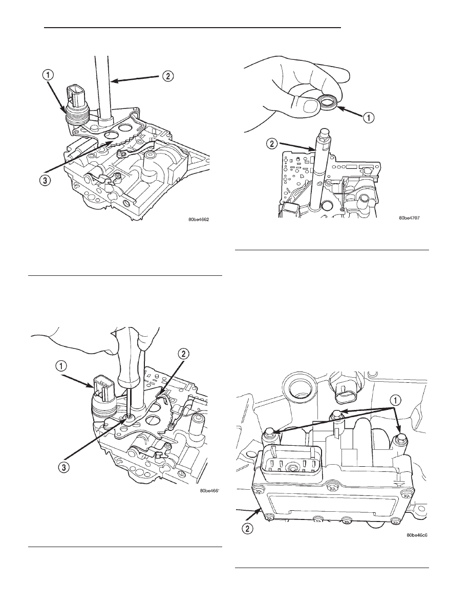
tained within the rooster comb slot (Fig. 139). Install
Transmission Range Sensor retaining screw (Fig.
139) and torque to 5 N·m (45 in. lbs.).

(18) Install manual shaft seal (Fig. 140).

TRANSAXLE—DISASSEMBLY

NOTE: Tag all clutch pack assemblies, as they are
removed, for reassembly identification.

CAUTION: Do not intermix clutch discs or plates as
the unit might then fail.

(1) Remove input and output speed sensors.
(2) Remove

the

three

solenoid/pressure

switch

assembly-to-transaxle case bolts (Fig. 141).

Fig. 138 Install Manual Shaft/Rooster Comb and

Transmission Range Sensor

1 – TRANSMISSION RANGE SENSOR
2 – MANUAL SHAFT
3 – ROOSTER COMB

Fig. 139 Install Transmission Range Sensor

Retaining Screw

1 – TRANSMISSION RANGE SENSOR
2 – MANUAL VALVE CONTROL PIN
3 – RETAINING SCREW

Fig. 140 Manual Shaft Seal

1 – SEAL
2 – MANUAL SHAFT

Fig. 141 Attaching Bolts

1 – BOLTS
2 – SOLENOID AND PRESSURE SWITCH ASSEMBLY

JX

TRANSAXLE

21 - 59

DISASSEMBLY AND ASSEMBLY (Continued)

(3) Remove solenoid/pressure switch assembly and

gasket (Fig. 142).

Fig. 142 Solenoid/Pressure Switch Assembly and

Gasket

1 – SOLENOID/PRESSURE SWITCH ASSEMBLY
2 – GASKET

Fig. 143 Remove Oil Pan Bolts

1 – OIL PAN BOLTS (USE RTV UNDER BOLT HEADS)

Fig. 144 Remove Oil Pan

1 – OIL PAN
2 – 1/8 INCH BEAD OF RTV SEALANT
3 – OIL FILTER

Fig. 145 Remove Oil Filter

1 – OIL FILTER
2 – O-RING

21 - 60

TRANSAXLE

JX

DISASSEMBLY AND ASSEMBLY (Continued)

NOTE: To ease removal of the valve body, turn the
manual valve fully clockwise.

CAUTION: Do not handle the valve body from the
manual valve. Damage could result.

Fig. 146 Remove Valve Body Attaching Bolts

1 – VALVE BODY ATTACHING BOLTS (18)
2 – VALVE BODY

Fig. 147 Push Park Rod Rollers from Guide Bracket

1 – PARK SPRAG ROLLERS
2 – SCREWDRIVER
3 – PARK SPRAG GUIDE BRACKET

Fig. 148 Remove Valve Body

1 – VALVE BODY

Fig. 149 Valve Body Removed

1 – VALVE BODY
2 – TRANSMISSION RANGE SENSOR

JX

TRANSAXLE

21 - 61

DISASSEMBLY AND ASSEMBLY (Continued)

NOTE: Dependent

on

engine

application,

some

accumulators will have two springs and others will
have one spring. The springs are color coded
according to application and year. When disassem-
bling, mark accumulator spring location to ease
assembly.

Fig. 150 Remove Underdrive and Overdrive

Accumulators

1 – RETURN SPRING
2 – UNDERDRIVE CLUTCH ACCUMULATOR
3 – SEAL RING (2)
4 – OVERDRIVE CLUTCH ACCUMULATOR

Fig. 151 Accumulator (Underdrive)

1 – ACCUMULATOR PISTON (UNDERDRIVE)
2 – RETURN SPRINGS
3 – SEAL RING
4 – SEAL RING

Fig. 152 Accumulator (Overdrive)

1 – ACCUMULATOR PISTON (OVERDRIVE)
2 – RETURN SPRING
3 – SEAL RING
4 – SEAL RING

Fig. 153 Remove Low/Reverse Accumulator Snap

Ring

1 – SNAP RING
2 – PLUG

21 - 62

TRANSAXLE

JX

DISASSEMBLY AND ASSEMBLY (Continued)


Content   ..  78  79  80  81   ..