Chrysler Stratus Convertible. Manual - part 52
 

  Index      Chrysler     Chrysler Stratus Convertible - service repair manual 1995-2000 year


Search            


Content   ..  50  51  52  53   ..


Chrysler Stratus Convertible. Manual - part 52


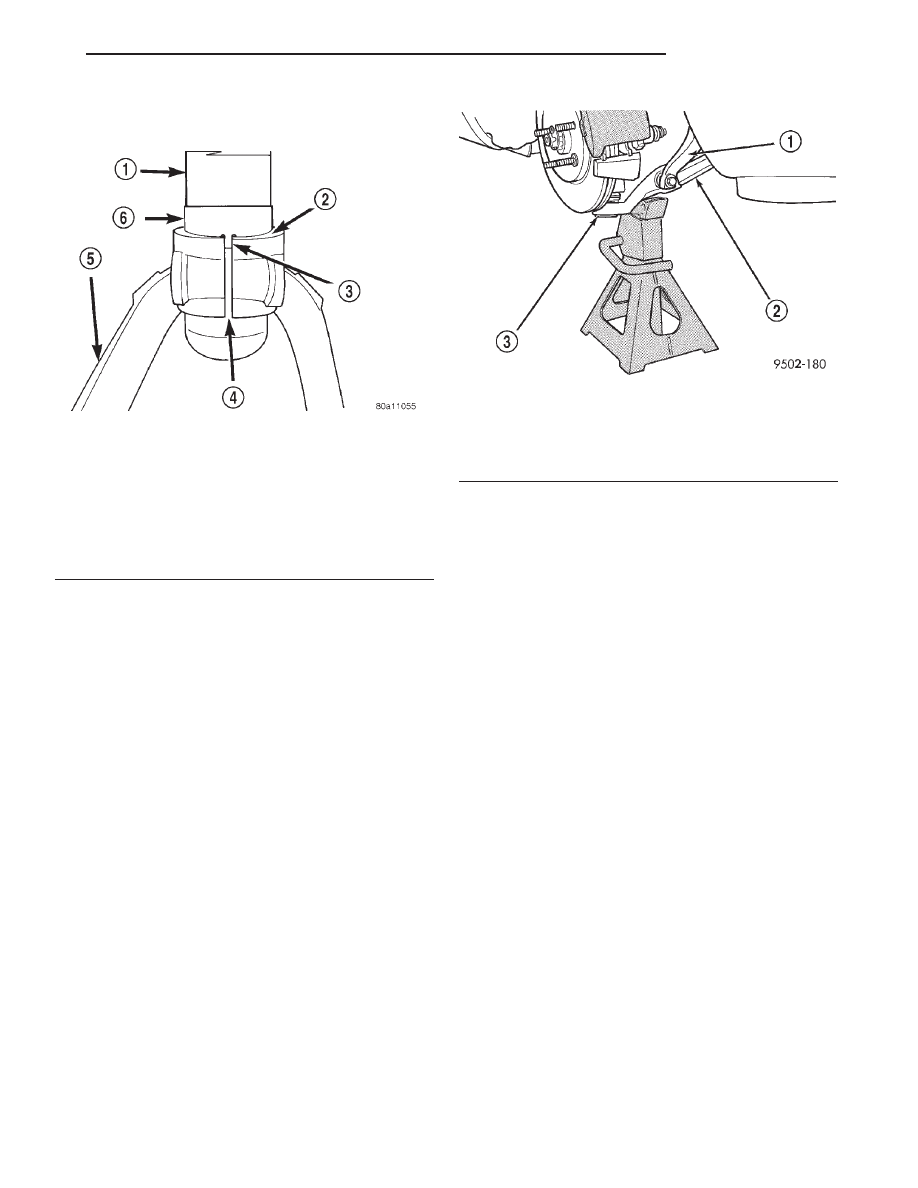
(Fig. 12). Orientation tab on locating tab must be
positioned in the split of the clevis (Fig. 12).

(3) Install the pinch bolt retaining the shock clevis

to the shock absorber (Fig. 9). Tighten the pinch bolt
to a torque of 88 N·m (65 ft. lbs.)

(4) Install the clevis bracket to lower control arm

thru-bolt (Fig. 10). Do not tighten or torque the thru-
bolt at this time.

(5) Install upper ball joint into steering knuckle.

Install castle nut on ball joint stud. Tighten castle
nut to a torque of 54 N·m (40 ft. lbs.). Install cotter
pin in stud of ball joint (Fig. 7).

(6) Install the routing bracket for the speed control

cable (Fig. 6) on the steering knuckle. Install and
securely tighten the routing bracket attaching bolt
(Fig. 6).

CAUTION: When supporting lower control arm with
jack stand, do not position jack stand under the ball
joint cap on the lower control arm. Position in area
of lower control arm shown in (Fig. 13).

(7) Lower vehicle to the ground with a jack stand

positioned under the lower control arm (Fig. 13).
Continue to lower vehicle so the total weight of the
vehicle is supported by the jack stand and lower con-
trol arm.

(8) Tighten the shock absorber clevis to lower con-

trol arm bushing thru-bolt nut to a torque of 88 N·m
(65 ft. lbs.).

(9) Raise the vehicle, then remove the jack stand.

(10) Install the tire and wheel assembly. Tighten

the wheel mounting stud nuts in proper sequence
until all nuts are torqued to half specification. Then
repeat the tightening sequence to the full specified
torque of 135 N·m (100 ft. lbs.).

(11) Lower the vehicle.

STEERING KNUCKLE

REMOVAL

(1) Raise vehicle on jack stands or centered on a

frame contact type hoist. See Hoisting in the Lubri-
cation and Maintenance section of this manual, for
the required lifting procedure to be used for this
vehicle.

(2) Remove front tire and wheel assembly from the

hub.

CAUTION: Wheel bearing damage will result if hub
nut is loosened, then vehicle is rolled on the
ground or the weight of the vehicle is allowed to be
supported by the tires.

(3) Loosen hub nut with the brakes applied. The

hub

and

driveshaft

are

splined

together

through the knuckle (bearing) and retained by
the hub nut.

(4) Remove front disc brake caliper to steering

knuckle guide pin attaching bolts (Fig. 14).

(5) Remove disc brake caliper assembly from steer-

ing knuckle. Caliper is removed by first lifting bot-
tom of caliper away from steering knuckle, and then
removing top of caliper out from under steering
knuckle (Fig. 15).

Fig. 12 Clevis Correctly Installed On Shock

Absorber

1 – SHOCK ABSORBER
2 – SHOCK CLEVIS MUST BE INSTALLED FLUSH AGAINST

LOCATING TAB HERE

3 – ORIENTATION TAB
4 – CLEVIS SPLIT
5 – SHOCK CLEVIS
6 – LOCATING TAB

Fig. 13 Lower Control Arm Correctly Supported By

Jack Stand

1 – SHOCK ABSORBER CLEVIS
2 – LOWER CONTROL ARM
3 – BALL JOINT CAP

JX

SUSPENSION

2 - 17

REMOVAL AND INSTALLATION (Continued)

(6) Support brake caliper/adapter assembly using a

wire hook (Fig. 16) and not by hydraulic hose.

(7) Remove the braking disc from the front hub/

bearing assembly.

(8) Remove nut attaching outer tie rod end to the

steering knuckle (Fig. 17). Nut is to be removed
from tie rod end using the following procedure,
hold tie rod end stud with a 11/32 socket while
loosening and removing nut with wrench (Fig.
17).

(9) Remove the tie rod end from the steering

knuckle using Remover, Special Tool MB-991113 (Fig.
18).

(10) Remove

the

speed

sensor

cable

routing

bracket (Fig. 19) from the steering knuckle.

(11) Remove cotter pin and castle nut (Fig. 20)

from the stud of the lower ball joint.

Fig. 14 Front Disc Brake Caliper Mounting

1 – DISC BRAKE CALIPER ASSEMBLY
2 – STEERING KNUCKLE
3 – CALIPER ASSEMBLY GUIDE PIN BOLTS

Fig. 15 Disc Brake Caliper Removal

1 – ROTOR
2 – DISC BRAKE CALIPER ASSEMBLY
3 – OUTBOARD BRAKE SHOE
4 – STEERING KNUCKLE
5 – LIFT THIS END OF CALIPER AWAY FROM STEERING

KNUCKLE FIRST

Fig. 16 Correctly Supported Front Disc Brake

Caliper

1 – ABS SPEED SENSOR CABLE
2 – STEERING KNUCKLE
3 – ROTOR
4 – UPPER CONTROL ARM
5 – DISC BRAKE CALIPER ASSEMBLY
6 – WIRE HANGER

Fig. 17 Tie Rod End Attaching Nut

1 – TIE ROD END
2 – HEAT SHIELD
3 – STEERING KNUCKLE
4 – TIE ROD END STUD
5 – NUT

2 - 18

SUSPENSION

JX

REMOVAL AND INSTALLATION (Continued)

CAUTION: No tool is to be inserted between the
steering knuckle and the lower ball joint to separate
stud of lower ball joint from the steering knuckle.
The steering knuckle is to be separated from the
stud of the ball joint only using the procedure as
described in step Step 12 below.

CAUTION: When striking the steering knuckle, do
not hit the heat shield covering the ball joint grease
seal. Bending the heat shield against the ball joint
grease seal will cause the grease seal to fail.

(12) Turn steering knuckle so the front of the

steering knuckle is facing as far outboard in the
wheel well as possible. Using a hammer strike the
boss on the steering knuckle, (Fig. 21) until the
steering knuckle separates from the stud of lower
ball joint.

Fig. 18 Tie Rod End Removal From Steering

Knuckle

1 – SPECIAL TOOL MB-991113
2 – TIE ROD END
3 – HEAT SHIELD
4 – STEERING KNUCKLE
5 – LOWER CONTROL ARM

Fig. 19 Speed Sensor Cable Routing Bracket

1 – WHEEL SPEED SENSOR CABLE
2 – SPEED SENSOR CABLE ROUTING BRACKET
3 – STEERING KNUCKLE
4 – ATTACHING BOLT
5 – BRAKE CALIPER FLEX HOSE

Fig. 20 Lower Ball Joint Attachment To Steering

Knuckle

1 – DRIVESHAFT
2 – COTTER PIN
3 – CASTLE NUT
4 – HEAT SHIELD
5 – LOWER CONTROL ARM
6 – SHOCK ABSORBER CLEVIS

Fig. 21 Separating Ball Joint Stud From Steering

Knuckle

1 – HAMMER
2 – BALL JOINT STUD
3 – STEERING KNUCKLE BOSS
4 – HEAT SHIELD
5 – LOWER CONTROL ARM

JX

SUSPENSION

2 - 19

REMOVAL AND INSTALLATION (Continued)

CAUTION: Pulling steering knuckle out from vehi-
cle after releasing from ball joint can separate inner
C/V joint. See Driveshafts.

(13) Lift up on steering knuckle separating it from

the lower ball joint stud. Use caution when sepa-
rating ball joint stud from steering knuckle, so
ball joint seal does not get cut.

NOTE: Care must be taken not to separate the
inner C/V joint during this operation. Do not allow
driveshaft to hang by inner C/V joint, driveshaft
must be supported.

(14) Separate the steering knuckle from the outer

C/V joint. Separate steering knuckle from outer C/V
joint, by supporting the driveshaft while pulling
steering knuckle away from the outer C/V joint (Fig.
22).

(15) Remove the cotter pin and nut (Fig. 23) from

the upper ball joint stud to steering knuckle attach-
ment.

(16) Remove the upper ball joint stud from the

steering knuckle using Puller, Special Tool, C-3894-A
(Fig. 24).

(17) Remove steering knuckle from vehicle.
(18)

The bolt in type front wheel bearing

used on the vehicle is transferable to the
replacement steering knuckle if bearing is
found to be in usable condition. 
Refer to Hub
And Bearing Service in this section of the service
manual for proper wheel bearing removal and instal-
lation procedure.

INSTALLATION

(1) If required install a hub/bearing assembly into

the

steering

knuckle

before

installing

steering

knuckle on vehicle. Refer to Hub And Bearing Ser-
vice in this section of the service manual for proper
wheel bearing removal and installation procedure.

Fig. 22 Separating Steering Knuckle From Outer C/V

Joint

1 – HUB/BEARING
2 – BEARING SHIELD
3 – OUTER C/V JOINT
4 – STEERING KNUCKLE

Fig. 23 Upper Ball Joint Attachment To Steering

Knuckle

1 – UPPER CONTROL ARM SHOCK ABSORBER MOUNTING

BRACKET

2 – BALL JOINT
3 – SHOCK ABSORBER ASSEMBLY
4 – STEERING KNUCKLE
5 – COTTER PIN
6 – CASTLE NUT
7 – UPPER CONTROL ARM

Fig. 24 Ball Joint Stud Removal From Steering

Knuckle

1 – BALL JOINT
2 – BALL JOINT STUD
3 – SPECIAL TOOL C3894–A
4 – SHOCK ABSORBER ASSEMBLY
5 – UPPER CONTROL ARM

2 - 20

SUSPENSION

JX

REMOVAL AND INSTALLATION (Continued)


Content   ..  50  51  52  53   ..