Chrysler Stratus Convertible. Manual - part 41
 

  Index      Chrysler     Chrysler Stratus Convertible - service repair manual 1995-2000 year


Search            


Content   ..  39  40  41  42   ..


Chrysler Stratus Convertible. Manual - part 41


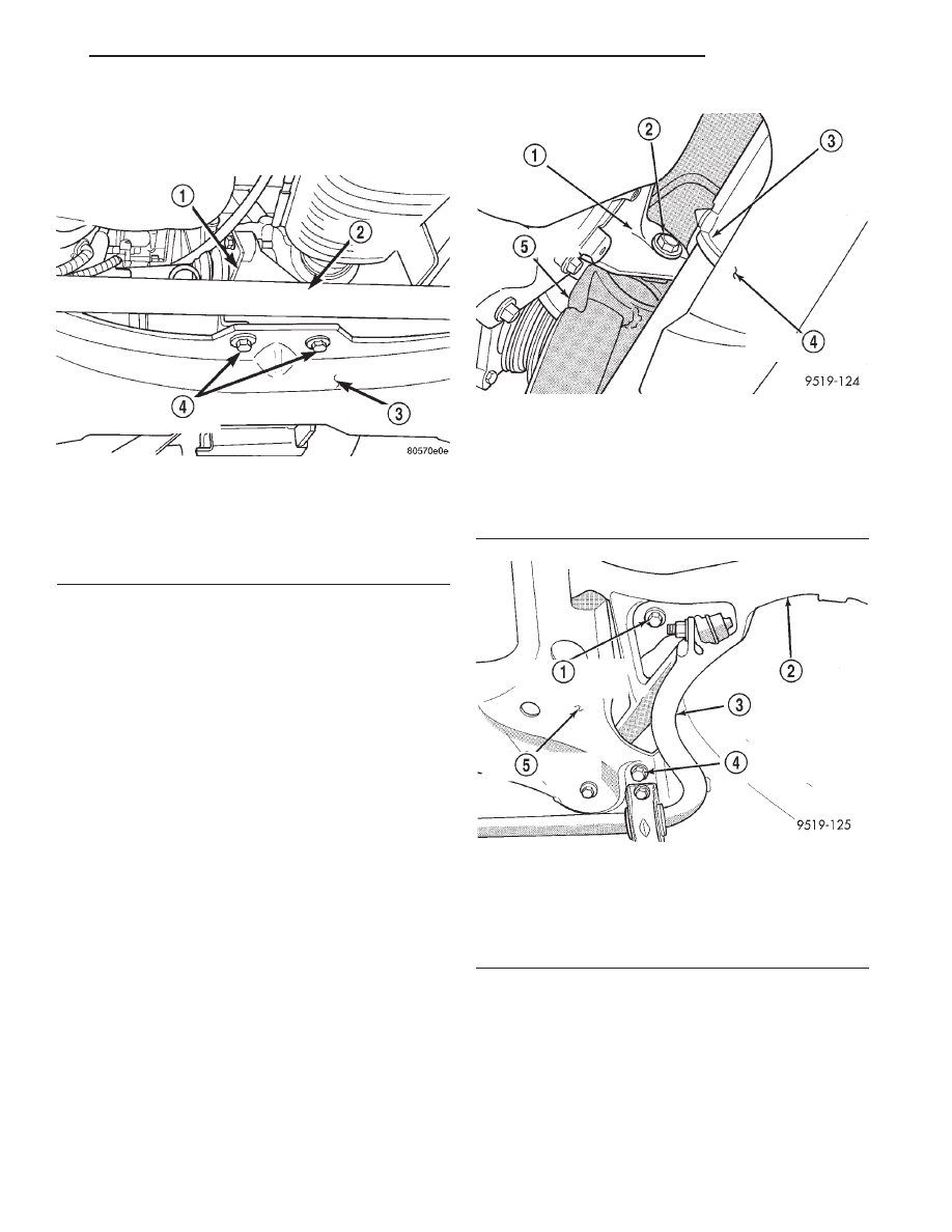
(16) Remove the 2 attaching bolts from the rear

support bracket (Fig. 17) at the rear of the front sus-
pension crossmember.

(17) Remove bolt (Fig. 18) attaching engine sup-

port bracket to the transaxle mounting bracket.

(18) Position a transmission jack under the center

of the front suspension crossmember. Transmission
jack is used to lower, support and raise front suspen-
sion crossmember when removing steering gear
assembly.

(19) From each side of the vehicle, remove the 2

bolts attaching the front and rear of the front sus-
pension crossmember to the frame rails of vehicle
(Fig. 19).

(20) Using transmission jack, lower front suspen-

sion crossmember enough to allow steering gear to be
removed from crossmember. When lowering front
suspension crossmember, do not let crossmem-
ber hang from lower control arms, weight of
crossmember must be supported by the trans-
mission jack.

(21) Remove power steering fluid, pressure and

return hoses from the power steering gear assembly
(Fig. 20).

Fig. 17 Rear Support Bracket Attachment To

Crossmember

1 – REAR SUPPORT BRACKET
2 – STABILIZER BAR
3 – CROSSMEMBER
4 – ATTACHING BOLTS

Fig. 18 Engine Support Bracket To Transaxle

Bracket Bolt

1 – TRANSAXLE MOUNTING BRACKET
2 – BOLT
3 – STEERING GEAR
4 – FRONT SUSPENSION CROSSMEMBER
5 – ENGINE SUPPORT BRACKET

Fig. 19 Crossmember To Body Attaching Bolts

1 – CROSSMEMBER FRONT MOUNTING BOLT
2 – LOWER CONTROL ARM
3 – STABILIZER BAR
4 – CROSSMEMBER REAR MOUNTING BOLT
5 – FRONT SUSPENSION CROSSMEMBER

JX

STEERING

19 - 41

REMOVAL AND INSTALLATION (Continued)

(22) Remove wiring harness connector, (Fig. 20)

from the power steering fluid pressure switch.

(23) Remove the 2 bolts, at the isolators (Fig. 21)

and (Fig. 22) attaching the steering gear assembly to
front suspension crossmember. Then remove the 2
bolts attaching the steering gear saddle bracket
(Fig. 23) to the front suspension crossmember.
Remove the steering gear assembly from the front
suspension crossmember.

(24) Transfer required parts from removed steering

gear assembly to the replacement steering gear, if a
new steering gear is being installed.

INSTALLATION

(1) Install steering gear assembly on front suspen-

sion crossmember. Install the 2 long steering gear
assembly

to

front

crossmember

mounting

bolts

(Fig. 21) and (Fig. 22) into the mounting isolators.
Then install the 2 short bolts (Fig. 23) into the sad-
dle bracket. Tighten the 4 steering gear mounting
bolts to a torque of 68 N·m (50 ft. lbs.).

Fig. 20 Power Steering Pressure And Return Hose

At Steering Gear

1 – POWER STEERING PRESSURE HOSE
2 – POWER STEERING RETURN HOSE
3 – POWER STEERING GEAR

Fig. 21 Steering Gear Rear Mounting Isolator Bolt

1 – REAR MOUNTING BOLT
2 – STEERING GEAR
3 – FRONT SUSPENSION CROSSMEMBER

Fig. 22 Steering Gear Front Mounting Bolt

1 – FRONT MOUNTING BOLT
2 – STEERING GEAR
3 – FRONT SUSPENSION CROSSMEMBER

Fig. 23 Steering Gear Saddle Bracket Mounting

Bolts

1 – ATTACHING BOLTS (2)
2 – SUPPORTED ANTILOCK BRAKES HYDRAULIC CONTROL

UNIT

3 – FRONT SUSPENSION CROSSMEMBER
4 – SADDLE BRACKET
5 – ISOLATOR
6 – STEERING GEAR

19 - 42

STEERING

JX

REMOVAL AND INSTALLATION (Continued)

(2) Install the power steering fluid pressure and

return lines on the ports of the power steering gear
(Fig. 20). Tighten power steering fluid pressure and
return lines to steering gear tube nuts (Fig. 20) to a
torque of 31 N·m (275 in. lbs.).

(3) Using transmission jack, raise front suspension

crossmember and steering gear against body of vehi-
cle. Start the 2 rear bolts (Fig. 19) into tapping
plates, attaching front suspension crossmember to
body of vehicle. Then install the 2 front bolts,
(Fig. 19) attaching front suspension crossmember to
frame rails of vehicle. Tighten the 4 mounting bolts
evenly, until front suspension crossmember is against
body of vehicle at the 4 mounting points. Then torque
the 4 mounting bolts to 2 N·m (20 in. lbs.) to hold
front suspension crossmember in position.

CAUTION: When front suspension crossmember
is installed back in vehicle, crossmember MUST
be aligned with positioning marks previously
scribed into body of vehicle. This MUST be done
to maintain NET BUILD front suspension align-
ment settings.

(4) Using a soft face hammer, tap front suspension

crossmember into position, until it is aligned with the
previously scribed positioning marks on body of vehi-
cle (Fig. 11), (Fig. 12) and (Fig. 13). When front sus-
pension crossmember is correctly positioned, torque
the 2 rear crossmember mounting bolts to 163 N·m
(120 ft. lbs.). Then torque the 2 front crossmember to
frame rail attaching bolts to 163 N·m (120 ft. lbs.).

(5) Install the engine support bracket on the front

of the front suspension crossmember (Fig. 16). Install
the 2 support bracket to suspension crossmember
attaching bolts and tighten to a torque of 75 N·m
(55 ft. lbs.).

(6) Install bolt (Fig. 18) attaching engine support

bracket to transaxle mounting bracket. Tighten bolt
to a torque of 75 N·m (55 ft. lbs.).

(7) Install the 2 bolts attaching the rear support

bracket,

for

the

under

engine

support

bracket

(Fig. 17), to the rear of the front suspension cross-
member. Tighten bolts to a torque of 75 N·m
(55 ft. lbs.).

(8) Install vehicle wiring harness connector onto

power steering fluid pressure switch on steering gear
assembly (Fig. 20). Be sure locking tab on wiring
harness connector is securely latched to pres-
sure switch.

(9) Install the antilock brakes hydraulic control

unit mounting bracket on the front suspension cross-
member. Install the 3 mounting bracket to crossmem-
ber attaching bolts and tighten to a torque of 28 N·m
(250 in. lbs.).

(10) Loosely install the 2 shock absorber clevis to

lower control arm attaching nuts and bolts (Fig. 15).

(11) Install tie rod seal boot heat shield on tie rod

end (Fig. 10).

(12) Install tie rod end into steering knuckle. Start

tie rod end to steering knuckle attaching nut onto
stud of tie rod end. While holding stud of tie rod end
stationary, tighten tie rod end to steering knuckle
attaching nut (Fig. 10). Then using a crowfoot and
11/32 socket, torque tie rod end attaching nut to 61
N·m (45 ft. lbs.) (Fig. 24).

(13) Install and tighten the 2 stabilizer bar bush-

ing clamp to body attaching bolts (Fig. 14).

CAUTION: When supporting lower control arm with
jack stand, do not position jack stand under the ball
joint cap on the lower control arm. Position in area
of lower control arm shown in (Fig. 25).

(14) Lower vehicle to the ground with a jack stand

positioned under the lower control arm (Fig. 25).
Continue to lower vehicle so the total weight of the
vehicle is supported by the jack stand and lower con-
trol arm.

(15) Tighten the shock absorber clevis to lower

control arm bushing thru-bolt to a torque of 92 N·m
(68 ft. lbs.).

(16) Install the wheel and tire assemblies back on

vehicle. Tighten the wheel nuts in proper sequence to
a torque of 129 N·m (95 ft. lbs.) (Fig. 15).

Fig. 24 Torquing Tie Rod End Attaching Nut

1 – HEAT SHIELD
2 – TIE ROD END
3 – STEERING KNUCKLE
4 – TORQUE WRENCH
5 – 11/32 SOCKET
6 – CROWFOOT

JX

STEERING

19 - 43

REMOVAL AND INSTALLATION (Continued)

CAUTION: Before connecting the steering column
intermediate shaft coupler to the steering gear
shaft, position the front wheels STRAIGHT-AHEAD.
The steering wheel must also be in the centered
position.

(17) Under the instrument panel, reconnect the

intermediate shaft to the steering gear shaft. To do
so, perform one of the following that applies:

(a) On early production vehicles, reconnect the

steering column intermediate shaft to the steering
gear shaft (Fig. 7). Install a new intermediate
shaft coupler pinch bolt through the coupler and
into its nut, then tighten the nut and pinch bolt to
a torque of 27 N·m (240 in. lbs.).

(b) On later production vehicles, align the flats

and slide the intermediate shaft onto the steering
gear shaft aligning the pinch bolt hole with the
notch formed into the steering gear shaft. Install a
new pinch bolt in the intermediate shaft coupler
(Fig. 8), then tighten the pinch bolt to a torque of
34 N·m (300 in. lbs.).
(18) On early production vehicles, install a new

“E” clip on the end of the pinch bolt (Fig. 7).

(19) Remove the steering wheel holder.

CAUTION: Do not use automatic transmission fluid
in place of power steering fluid.

(20) Fill power steering pump fluid reservoir to the

(Full-Cold) proper level.

(21) Start the engine and let it run for a few sec-

onds to circulate the fluid.

(22) Turn the engine off.
(23) Add fluid if necessary.

(24) Raise front wheels of vehicle off the ground.
(25) Start engine and turn steering wheel several

times from stop-to-stop to bleed air from fluid in sys-
tem. Stop engine, check fluid level, and inspect sys-
tem for leaks. Fill pump reservoir to correct
level with Mopar

t, Power Steering Fluid, or

equivalent. See Checking Fluid Level.

(26) Lower front wheels of vehicle back on the

ground.

CAUTION: During this procedure do not allow the
steering gear inner tie rod boots to become twisted.
(See Wheel Alignment in the suspension section of
this service manual).

(27) Check front alignment and adjust the front

Toe setting on the vehicle. Refer to the Toe Setting
Procedure in Front Suspension Service Procedures in
this group of the service manual. Refer to the Speci-
fications Section at the end of this group for the
desired front Toe specification.

(28) Tighten tie rod jam nut to 74 N·m (55 ft. lbs.)

torque.

(29) Adjust steering gear to tie rod boots at tie

rods.

OUTER TIE ROD END

DISASSEMBLE

(1) Loosen inner tie rod to outer tie rod jam nut

(Fig. 26).

(2) Remove nut attaching outer tie rod end to

steering knuckle (Fig. 27). Nut is to be removed
from tie rod end using the following procedure,
hold tie rod end stud with a 11/32 socket while
loosening and removing nut with wrench.

Fig. 25 Lower Control Arm Correctly Supported By

Jack Stand

1 – SHOCK ABSORBER CLEVIS
2 – LOWER CONTROL ARM
3 – BALL JOINT CAP

Fig. 26 Inner To Outer Tie Rod Jam Nut

1 – OUTER TIE ROD
2 – INNER TIE ROD
3 – JAM NUT

19 - 44

STEERING

JX

REMOVAL AND INSTALLATION (Continued)


Content   ..  39  40  41  42   ..