Chrysler New Yorker. Manual - part 277


  Index      Chrysler     Chrysler New Yorker - service repair manual 1997-1999 year


Search            


Content   ..  275  276  277  278   ..


Chrysler New Yorker. Manual - part 277


the roll pin retaining the intermediate shaft flex cou-
pler to the steering gear shaft.

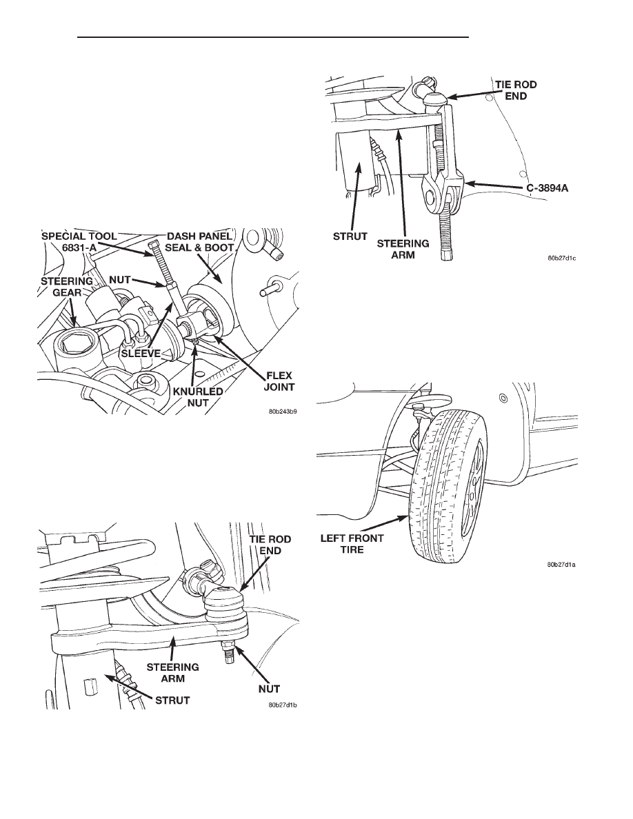
(22) Using roll pin remover, Special Tool 6831A,

remove roll pin from flex joint of intermediate shaft
(Fig. 17). Roll pin is removed from coupler using fol-
lowing procedure. Remove knurled nut from small
end of removal tool. Insert small end of removal tool
through center of roll pin and then install and hand
tighten knurled nut. Position sleeve of removal tool
on flex joint as shown in (Fig. 17). Holding threaded
shaft of tool from turning tighten nut (Fig. 17) pull-
ing roll pin out of flex joint.

(23) Separate the intermediate steering shaft from

the steering gear.

(24) Raise vehicle.
(25) Remove the right front tire/wheel.
(26) Remove the nut (Fig. 18) attaching the tie rod

end to the steering arm on the right strut.

(27) Remove the tie rod end from the steering arm

of the strut using Puller, Special Tool C-3894–A (Fig.
19).

(28) Remove the tie rod from the vehicle.

NOTE: If the vehicle is equipped with a 2.7 liter
engine, rotate the front of the left front tire/wheel as
far outward as possible (Fig. 20). This is necessary
to have the required clearance to allow the removal
of the steering gear from a vehicle with this engine
application.

(29) Remove the steering gear from the vehicle

using the following steps.

(a) Slide the end of the steering gear through

the tie rod hole in the right side inner fender (Fig.
21). Steering gear needs to be slid through tie rod
hole until about half of the steering gear is through
the hole (Fig. 21).

(b) Lift the left end of the steering gear upward ,

with

the

steering

gear

positioned

as

shown,

between the back of the engine and the front of the
cowl (Fig. 22).

(c) To remove the steering gear from the vehicle,

pull the steering gear toward the passenger side of
the vehicle out from between the cowl and the
engine.

Fig. 17 Steering Coupler Roll Pin Removal

Fig. 18 Tie Rod End Attachment To Strut

Fig. 19 Tie Rod End Removal From Steering Arm

Fig. 20 Required Tire Position

300M

STEERING

19 - 33

REMOVAL AND INSTALLATION (Continued)

INSTALL

NOTE: When the original or a replacement steering
gear is being installed in vehicle, be sure the tie rod
attachment at the steering gear is in the center of
steering gear travel.

(1) Install the steering gear in the vehicle using

the reverse sequence of the removal steps.

NOTE: If the vehicle is equipped with a 2.7 Liter
engine, position the left front tire so it is facing
straight forward.

(2) Install the right tie rod through the tie rod hole

in the inner fender.

(3) Install the outer tie rod on the steering arm of

the right strut. Install the tie rod to steering arm
attaching nut (Fig. 18). Tighten the attaching nut to
a torque of 37 N·m (27 ft. lbs.).

(4) Install the right side tire/wheel.
(5) Install and tighten wheel mounting stud nuts

in proper sequence until all nuts are torqued to half

specification. Then repeat the tightening sequence to
the full specified torque of 129 N·m (95 ft. lbs.).

(6) Lower the vehicle until the front tires are just

clear of the floor.

(7) Install the intermediate steering shaft on the

steering gear.

(8) Using roll pin installer, Special Tool 6831A,

install the roll pin in the flex joint of the intermedi-
ate shaft (Fig. 23). Roll pin is installed in coupler
using the following procedure. Remove knurled nut
from small end of removal tool. Insert small end of
removal tool through center of roll pin and then
install and hand tighten knurled nut. Position sleeve
of removal tool on flex joint as shown in (Fig. 23).
Holding threaded shaft of tool from turning tighten
nut (Fig. 23) pulling roll pin into flex joint. Roll pin
must be equally spaced in flex joint.

(9) Slide steering gear and intermediate shaft back

into dash panel sealing boot. Align the steering gear
mounting holes with its mounting holes in crossmem-
ber.

(10) Loosely install the bolts mounting the left side

of the steering gear to the crossmember (Fig. 14).

CAUTION: Tightening the steering gear to cross-
member mounting bolts to the proper torque is very
important.

(11) Install the bolts mounting the right side

mounting bracket for the steering gear to the cross-
member (Fig. 15). Tighten the mounting bolts to a
torque of 58 N·m (43 ft. lbs.).

(12) Tighten the bolts mounting the left side of the

steering gear to the crossmember to a torque of 58
N·m (43 ft. lbs.).

(13) If

previously

loosened,

tighten

the

bolts

mounting the steering gear mounting bracket to the
right side of the steering gear (Fig. 16) to a torque of
37 N·m (27 ft. lbs.).

Fig. 21 Steering Gear Through Tie Rod Hole

Fig. 22 Steering Gear Positioned For Removal

Fig. 23 Steering Coupler Roll Pin Installation

19 - 34

STEERING

300M

REMOVAL AND INSTALLATION (Continued)

CAUTION: Before installing tie rods on steering
gear be sure the tie rod spacer block inside the
steering gear bellows (boot) (Fig. 24) is correctly
aligned with the bolt holes in the rack of the steer-
ing gear and the steering gear bellows.

(14) Attach power steering fluid pressure, and

return lines into proper ports of the steering gear
(Fig. 11). Tighten both power steering hose tube nuts
to a torque of 47 N·m (35 ft. lbs.).

(15) If equipped with speed proportional steering,

connect the wiring harness connector to the solenoid
control valve electrical connector (Fig. 12).

(16) Align center take off on steering gear with the

tie rod assemblies. Install tie rod attaching bolts and
washers into steering gear assembly. Be sure wash-
ers are installed between tie rods and steering
gear (Fig. 25). Tighten the tie rod to steering
gear bolts to a torque of 82 N·m (60 ft. lbs.).

CAUTION: After tie rod attaching bolts are torqued,
bend attaching bolt retaining tabs against heads of
attaching bolts (Fig. 9).

(17) Install the vacuum hose for the vacuum

booster on intake manifold vacuum port. Install hose
clamp on vacuum hose.

(18) Install the master cylinder on the vacuum

booster. Install the 2 nuts attaching the master cyl-
inder to the vacuum booster. Tighten the master cyl-
inder mounting nuts to a torque of 28 N·m (250 in.
lbs.).

(19) Install the intermediate shaft onto the steer-

ing column shaft. Install steering column coupler
pinch bolt (Fig. 8) and tighten to a torque of 28 N·m
(21 ft. lbs.). Install the pinch bolt nut retaining pin in
pinch bolt.

(20) Remove the holding clamp from the steering

wheel (Fig. 7).

(21) Install the reinforcement (Fig. 5) on the vehi-

cle. Install the 8 bolts, attaching the reinforcement
(Fig. 5) to the strut towers. Install the bolt (Fig. 5)
attaching the wiper module to the reinforcement.

(22) Install the in-line resonator and inlet hose

(Fig. 6) on the throttle body and air let hose coming
from the lid of the air cleaner housing.

(23) Install the covers (Fig. 4) over the wiper mod-

ule and the cowl. Install and securely tighten the
attaching screws.

(24) Install the wiper arms (Fig. 3) on the pivots.

Install and securely tighten the wiper arm to pivot
attaching nuts. Install the caps on the wiper arms
covering the pivot nuts.

(25) Install the battery ground cable onto the

ground stud on the shock tower.

CAUTION: Do not use automatic transmission fluid.
Use only the proper Mopar Power Steering Fluid or
equivalent when filling the power steering fluid res-
ervoir.

(26) Perform Power Steering Pump Initial Opera-

tion procedure which can be found in the Power
Steering Pump section of this group, to properly refill
and bleed power steering system.

(27) Lower vehicle.
(28) Adjust front toe. Refer to Suspension, Group

2, for the proper procedure.

OUTER TIE ROD

REMOVE

(1) Raise vehicle on jackstands or centered on a

frame contact type hoist. See Hoisting in the Lubri-
cation and Maintenance section of this manual for
the required lifting procedure to be used for this
vehicle.

Fig. 24 Tie Rod Spacer Block

Fig. 25 Tie Rod Attachment To Steering Gear

300M

STEERING

19 - 35

REMOVAL AND INSTALLATION (Continued)

(2) Remove tire and wheel assembly.
(3) Loosen the pinch bolt (Fig. 26) at the outer to

inner tie rod adjustment sleeve.

(4) Remove the outer tie rod to strut steering arm

attaching nut (Fig. 27).

(5) Remove the outer tie rod from the steering arm

using Puller, Special Tool C-3894-A (Fig. 28).

(6) Remove outer tie rod from adjustment sleeve.

INSTALL

(1) Install the outer tie rod into the adjustment

sleeve. Do not tighten the adjustment pinch bolt
at this time.

(2) Install the outer tie rod into the steering arm

on front strut. Install tie rod to steering arm attach-
ing nut (Fig. 27). Tighten the attaching nut a torque
of 37 N·m (27 ft. lbs.).

(3) Install the tire and wheel assembly.
(4) Install and tighten the wheel mounting nuts in

proper sequence until all nuts are torqued to half

specification. Then repeat the tightening sequence to
the full specified torque of 129 N·m (95 ft. lbs.).

(5) Lower vehicle.

CAUTION: When setting the front Toe on the vehi-
cle, the maximum dimension of exposed threads
allowed on the adjuster and outer tie rod cannot
exceed the distance shown in (Fig. 29). If the maxi-
mum distance is exceeded, inadequate retention of
either the adjuster or the outer tie rod can result.
This condition can cause separation of the outer tie
rod end from the inner tie rod. Ensure that adjust-
ment sleeve pinch bolts are torqued to the required
specification when Toe setting procedure is com-
pleted.

(6) Check the front wheel toe setting on vehicle

and make required changes. When making front
wheel toe adjustments, be sure the maximum
exposed thread requirements (Fig. 29) are not
exceeded.

Fig. 26 Tie Rod Adjustment Sleeve Pinch Bolt

Fig. 27 Tie Rod Nut

Fig. 28 Tie Rod Removal From Steering Arm

Fig. 29 Tie Rod Thread Engagement Requirements

19 - 36

STEERING

300M

REMOVAL AND INSTALLATION (Continued)


Content   ..  275  276  277  278   ..