Chrysler New Yorker. Manual - part 62
DIAGNOSIS AND TESTING
IGNITION TIMING PROCEDURE
The engines for this vehicle, use a fixed ignition
system. The PCM regulates ignition timing. Basic
ignition timing is not adjustable.
CAMSHAFT POSITION SENSOR AND CRANKSHAFT
POSITION SENSOR
The output voltage of a properly operating cam-
shaft position sensor or crankshaft position sensor
switches from high (5.0 volts) to low (0.3 volts). By
connecting an Moper Diagonostic System (MDS) and
engine analyzer to the vehicle, technicians can view
the square wave pattern.
ENGINE COOLANT TEMPERATURE SENSOR
Refer to Group 14, Fuel System for Diagnosis and
Testing.
INTAKE AIR TEMPERATURE SENSOR
Refer to Group 14, Fuel System, for Diagnosis and
Testing.
MANIFOLD ABSOLUTE PRESSURE (MAP) SENSOR
TEST
Refer to Group 14, Fuel System for Diagnosis and
Testing.
THROTTLE POSITION SENSOR
To perform a complete test of the this sensor and
its circuitry, refer to the DRB scan tool and appropri-
ate Powertrain Diagnostics Procedures manual. To
test the throttle position sensor only, refer to the fol-
lowing:
The Throttle Position Sensor (TPS) can be tested
with a digital voltmeter (DVM). The center terminal
of the sensor is the output terminal. One of the other
terminals is a 5 volt supply and the remaining ter-
minal is ground.
Connect the DVM between the center and sensor
ground terminal. Refer to Group 8W - Wiring Dia-
grams for correct pinout.
With the ignition switch in the ON position, check
the output voltage at the center terminal wire of the
connector. Check the output voltage at idle and at
Wide-Open-Throttle (WOT). At idle, TPS output volt-
age should be approximately 0.38 volts to 1.2 volts.
At wide open throttle, TPS output voltage should be
approximately 3.1 volts to 4.4 volts. The output volt-
age should gradually increase as the throttle plate
moves slowly from idle to WOT.
Check for spread terminals at the sensor and PCM
connections before replacing the TPS.
SPARK PLUG CONDITION
NORMAL OPERATING CONDITIONS
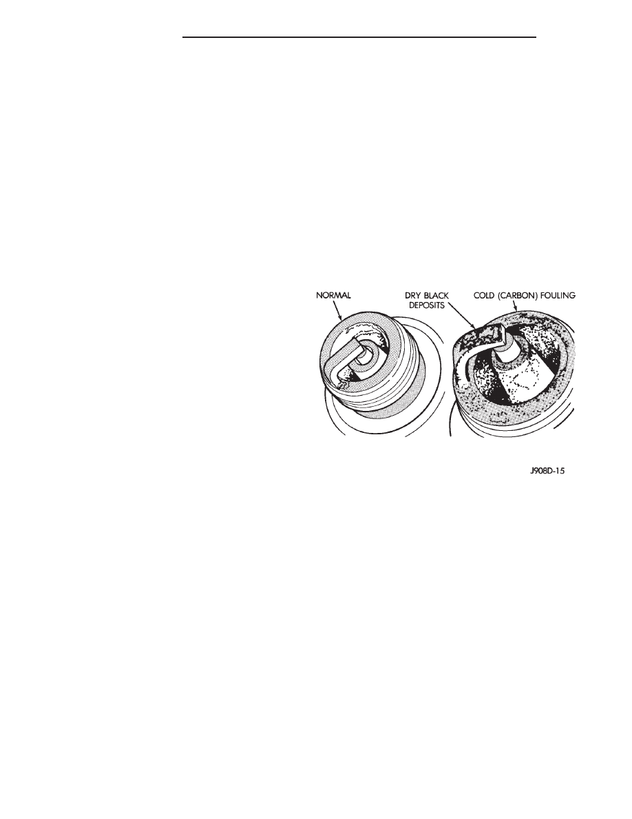
The few deposits present will be probably light tan
or slightly gray in color with most grades of commer-
cial gasoline (Fig. 19). There will not be evidence of
electrode burning. Gap growth will not average more
than approximately 0.025 mm (.001 in) per 1600 km
(1000 miles) of operation for non platinum spark
plugs. Non-platnium spark plugs that have normal
wear can usually be cleaned, have the electrodes filed
and regapped, and then reinstalled.
CAUTION: Never attempt to file the electrodes or
use a wire brush for cleaning platinum spark plugs.
This would damage the platinum pads which would
shorten spark plug life.
Some fuel refiners in several areas of the United
States have introduced a manganese additive (MMT)
for unleaded fuel. During combustion, fuel with MMT
may coat the entire tip of the spark plug with a rust
colored deposit. The rust color deposits can be misdi-
agnosed as being caused by coolant in the combustion
chamber. Spark plug performance is not affected by
MMT deposits.
COLD FOULING (CARBON FOULING)
Cold fouling is sometimes referred to as carbon
fouling because the deposits that cause cold fouling
are basically carbon (Fig. 19). A dry, black deposit on
one or two plugs in a set may be caused by sticking
valves or misfire conditions. Cold (carbon) fouling of
the entire set may be caused by a clogged air cleaner.
Cold fouling is normal after short operating peri-
ods. The spark plugs do not reach a high enough
operating temperature during short operating peri-
ods. Replace carbon fouled plugs with new
spark plugs.
Fig. 19 Normal Operation and Cold (Carbon) Fouling
8D - 8
IGNITION SYSTEM
300M