Chrysler Town & Country/Voyager, Dodge Caravan, Plymouth Voyager. Manual - part 298
inder head or camshaft, it is necessary to be certain
that oversized camshafts are used only in oversized
heads. Identify oversize components follows:
Cylinder Head: Top of bearing caps painted green
and O/SJ stamped rearward of oil gallery plug on end
of head.
Camshaft: Barrel of camshaft painted green and
O/SJ stamped on end of shaft.
CLEANING
Remove all gasket material from cylinder head and
block. Becareful not gouge or scratch aluminum head
sealing surface.
INSTALLATION
CAUTION: Head bolt diameter is 11mm. These bolts
are identified with 11 on the head of the bolt. 10mm
bolts will thread into the 11mm hole but will strip the
cylinder block bolt hole.
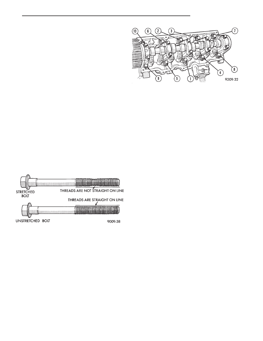
Since the Cylinder head bolts are torqued us-
ing a new procedure they should be examined
BEFORE reuse. If the threads are necked down
the bolts should be replaced (Fig. 15).
Necking can be checked by holding a scale or straight
edge against the threads. If all the threads do not
contact the scale the bolt should be replaced.
(1) Position new head gasket on the cylinder block.
(2) Tighten the cylinder head bolts in the sequence
shown in (Fig. 16). Using the 4 step torque turn
method, tighten according to the following values:
• First All to 61 NIm (45 ft. lbs.)
• Second All to 88 NIm (65 ft. lbs.)
• Third All (again) to 88 NIm (65 ft. lbs.)
• Fourth + 1/4 Turn Do use a not torque wrench
for this step.
Bolt torque after 1/4 turn should be over 90 ft.
lbs. If not, replace the bolt.
(3) Rotate dipstick tube on bracket.
(4) Tighten bracket retaining nut to 23 N
Im (200 in.
lbs.).
(5) Install cylinder head cover and curtain. Refer to
cover sealing of this group for procedure.
VALVE SERVICE—CYLINDER HEAD REMOVED
VALVES AND VALVE SPRINGS
REMOVAL
(1) With cylinder head removed, compress valve
springs using Tool C-3422-B.
(2) Remove valve retaining locks, valve spring re-
tainers, valve stem seals and valve springs.
(3) Before removing valves, remove any burrs
from valve stem lock grooves to prevent damage
to the valve guides. Identify valves to insure instal-
lation in original location.
VALVE INSPECTION
(1) Clean valves thoroughly and discard burned,
warped and cracked valves.
(2) Measure valve stems for wear.
(3) If valve stems are worn more than 0.05 mm (.002
inch.) replace valve.
VALVE GUIDES
(1) Remove carbon and varnish deposits from inside
of valve guides with a reliable guide cleaner.
(2) Checking Valve Guide Wear:
• Insert valve with valve head positioned 10 mm (.400
inch) above cylinder head gasket surface.
• Move valve to and from the indicator (Fig. 17). The
total dial indicator reading should not exceed the
amount specified in (Fig. 18). Readings should be taken
for lengthwise and crosswise (with respect to cylinder
head) movement for each valve. Ream the guides for
valves with oversize stems if dial indicator reading is
excessive or if the stems are scuffed or scored.
(3) Service valves with oversize stems and oversize
seals are available in 0.15mm, (.005 inch) 0.40mm,
(.015 inch) and 0.80mm(.031 inch) oversize.
Oversize seals must be used with oversize
valves.
Reamers sizes to accommodate the oversize valve
stem are shown in (Fig. 18).
(4) Slowly turn reamer by hand and clean guide
thoroughly before installing new valve. Do not at-
tempt to ream the valve guides from standard
Fig. 15 Checking Bolts for Stretching (Necking)
Fig. 16 Cylinder Head Tightening Sequence
.
2.5L ENGINE
9 - 23