Chrysler Town & Country/Voyager, Dodge Caravan, Plymouth Voyager. Manual - part 160
(6) Slide secondary shoe into position and engage
with wheel cylinder piston and free end of strut. Install
shoe retaining nail, retainer, and spring using In-
staller, Special Tool C-4070 (Fig. 4).
(7) Insert protruding hole rim of cable guide (Fig. 1
or 2) into hole in secondary shoe web. Holding guide in
position, engage secondary shoe return spring through
both, hole in guide, and hole in web. Using Installer,
Special Tool C-3785, install spring over anchor (Fig. 3).
(Be sure cable guide remains flat against shoe web and
that secondary spring overlaps primary (Fig. 1 & 2).
Using pliers, squeeze ends of spring loops (around
anchor) until parallel.
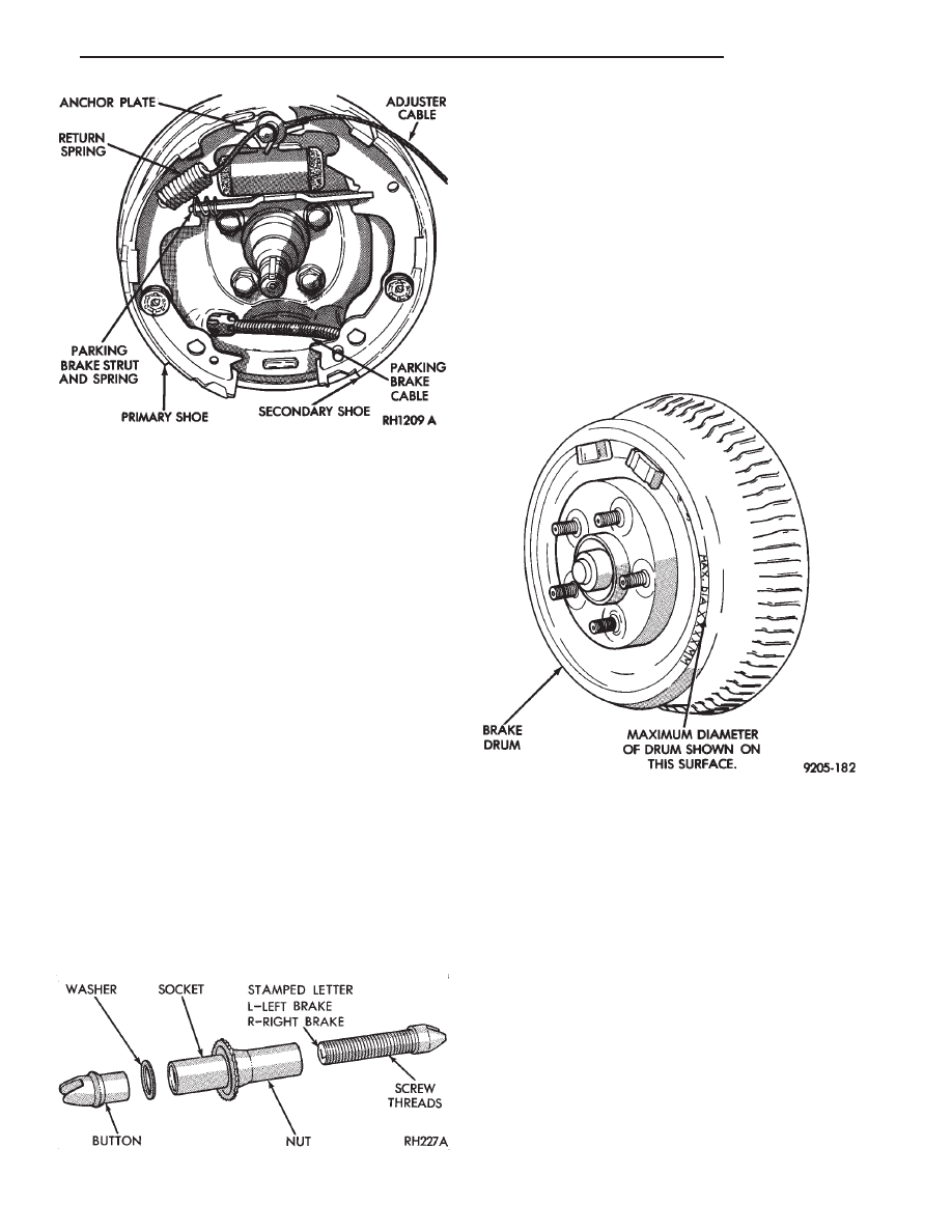
(8) Install adjuster screw assembly (Fig. 8) between
primary and secondary shoes, with star wheel of ad-
juster screw assembly next to secondary shoe (Fig. 1 &
2). The left star wheel adjusting stud end is stamped
(L) (indicating its position on the vehicle) and the star
wheel is cadmium plated (Fig. 8). The right star wheel
is black and the adjusting stud end is stamped (R).
Install shoe to shoe spring between shoes (Fig. 1).
(Engage primary shoe first).
(9) Install adjusting lever spring (Fig. 1 & 2) over
pivot pin on shoe web. Install adjusting lever under
spring and over pivot pin. Slide lever slightly rearward
to lock in position.
(10) Thread adjuster cable over guide and hook end
of overload spring in lever (Fig. 1 & 2). (Be sure eye of
cable is pulled tight against anchor and in a straight
line with guide). Check operation of automatic appli-
cation adjuster by pulling adjuster cable rearward, star
wheel should rotate upwards.
DRUM REFACING RECOMMENDATIONS
All drums will show markings of maximum
allowable diameter (Fig. 1). For example, a drum
will have a marking of MAX. DIA. 231.0 mm (9.09
inch). This marking includes 0.76 mm (0.030 inch)
for allowable drum wear beyond the recom-
mended 1.52 mm (0.060 inch) of drum refacing.
Drum Refacing Measure the drum runout and
diameter with an accurate gauge. There should be no
variation in the drum diameter greater than 0.090 mm
(0.004 inch). Drum runout should not exceed 0.15 mm
(0.006 inch) out of round. If the drum runout or
diameter variation exceed these values the drum
should be refaced. For best results in eliminating the
irregularities that cause brake roughness and surge,
the amount of material removed during a single cut
should be limited to 0.13 mm (0.005 inch). When the
entire braking surface has been cleaned. A final cut of
0.0254 mm (0.001 inch) will ensure a good drum
surface providing the equipment used is capable of the
precision required for resurfacing brake drums. Deeper
cuts are permissible for the sole purpose of removing
deep score marks. Do not reface more than 1.52 mm
(0.60 inch) over the standard drum diameter.
Fig. 7 Installing Parking Bake Cable
Fig. 8 Adjuster Screw Assembly
Fig. 1 Drum Maximum Diameter Identification
.
BRAKES
5 - 23