Chrysler Town & Country/Voyager, Dodge Caravan, Plymouth Voyager. Manual - part 149


  Index      Chrysler     Chrysler Town & Country/Voyager, Dodge Caravan, Plymouth Voyager - service repair manual 1992 year


Search            


Content   ..  147  148  149  150   ..


Chrysler Town & Country/Voyager, Dodge Caravan, Plymouth Voyager. Manual - part 149


CASE COVER SERVICE

DIFFERENTIAL CARRIER END COVER (RE-
SEAL)

(1) Remove left half shaft.
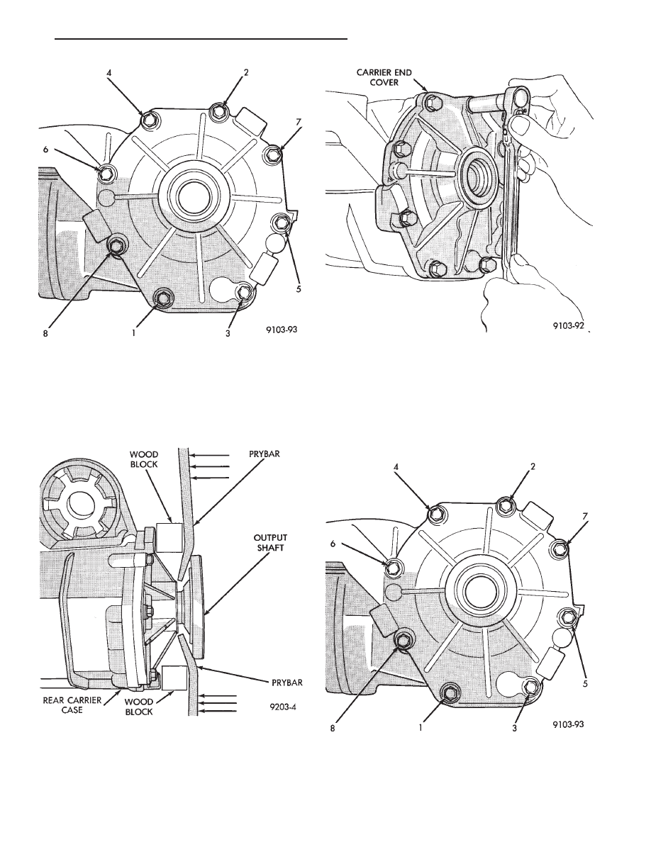
(2) Using two pry bars, pop out output shaft (Fig. 1).

(3) Remove output shaft.
(4) Remove end cover retaining bolts (Fig. 2).

(5) Remove differential end cover.
(6) Clean and inspect sealer surfaces.
(7) Apply Mopar

t Gasket Maker, Loctite Gasket

Eliminator or equivalent and install end cover. Tighten
to 28 N

Im (250 in. lbs.).

(8) Tighten bolts in the sequence shown in Fig. 3.

Retighten first bolt after all others are tight.

(9) Fill differential with lubricant.

Fig. 15 Bolt Tightening Sequence.

Fig. 1 Output Flange Removal

Fig. 2 Remove End Cover Bolts

Fig. 3 Bolt Tightening Sequence.

.

REAR SUSPENSION AND DRIVELINE

3 - 23

OVERRUNNING CLUTCH COVER (RESEAL)

(1) Remove rear drive line module assembly from

vehicle.

(2) Remove overrunning clutch cover assembly

mounting bolts (Fig. 4).

(3) Lift overrunning clutch cover off of overrunning

clutch housing.

(4) Clean and inspect sealing surfaces.
(5) Apply Mopar

t Gasket Maker, Loctite Gasket

Eliminator or equivalent and reinstall cover and
vacuum hose clip. When installing cover be sure that
the overrunning clutch fork engages into the overrun-
ning clutch dog.

(6) Install overrunning clutch cover mounting bolts

and tighten bolts to 28 N

Im (250 in. lbs.).

(7) Reinstall rear drive line module assembly into

vehicle.

(8) Check and fill fluid levels as required. Use only

MOPAR

t TYPE 7176 Automatic Transmission Fluid or

equivalent in the overrunning clutch case.

OVERRUNNING CLUTCH CASE TO REAR CAR-
RIER CASE (RESEAL)

(1) Remove rear drive line module assembly from

vehicle.

(2) Drain fluid from overrunning clutch case.
(3) Remove overrunning clutch case to rear carrier

bolts (Fig. 5).

(4) Separate overrunning clutch case from rear car-

rier unit (Fig. 6).

(5) Clean and inspect sealing surfaces.
(6) Apply a bead of Mopar

t Gasket Maker, Loctite

Gasket Eliminator or equivalent to sealing surfaces
and reassemble.

(7) Reinstall rear drive line module assembly.
(8) Check and fill fluid levels as required. Use only

MOPAR

t TYPE 7176 Automatic Transmission Fluid or

equivalent in the overrunning clutch housing.

Fig. 4 Mounting Bolts

Fig. 5 Overrunning Clutch Case to Rear Carrier

Bolts

Fig. 6 Separate Rear Carrier Case from Overrunning

Clutch Case

3 - 24

REAR SUSPENSION AND DRIVELINE

.

TORQUE

TUBE

AND

OVERRUNNING

CLUTCH

COMPONENTS

.

REAR SUSPENSION AND DRIVELINE

3 - 25

TORQUE TUBE

REMOVAL AND INSTALLATION

(1) Remove rear drive line module assembly from

vehicle.

(2) Remove viscous coupling.
(3) Remove snap ring and torque tube bearing shield

(Fig. 1).

(4) Remove torque tube to overrunning clutch case

bolts (Fig 2).

(5) Slide torque tube off of torque shaft.
(6) For Installation, Reverse Removal Procedure.

FRONT BEARING

REMOVAL AND INSTALLATION

The rear drive line module must be removed to

service this bearing.

(1) Remove rear drive line module assembly from

vehicle.

(2) Remove viscous coupling.
(3) Remove overrunning clutch cover assembly.
(4) Drain fluid from overrunning clutch case.
(5) Remove overrunning clutch case to rear carrier

case bolts (Fig. 3).

(6) Separate overrunning clutch case from differen-

tial carrier case (Fig. 4).

(7) Remove overrunning clutch inner race snap ring

(Fig. 5).

(8) Slide overrunning clutch inner race off of shaft

(Fig. 6).

(9) Remove shaft snap ring and slide dog clutch off of

the shaft.

(10) Remove torque shaft rear bearing snap ring.
(11) Remove overrunning case to torque tube bolts

(Fig. 7).

(12) Separate torque tube from overrunning clutch

housing.

(13) Remove front snap ring and torque tube bearing

shield (Fig. 8).

(14) Slide shaft out of torque tube.
(15) Drive bearing out of housing.
(16) To Install Bearing, Reverse Removal Procedure.

Fig. 1 Remove Torque Shaft Snap Ring and Torque

Tube Shield

Fig. 2 Torque Tube Bolts

Fig. 3 Overrunning Clutch Housing to Rear carrier

Bolts

3 - 26

REAR SUSPENSION AND DRIVELINE

.


Content   ..  147  148  149  150   ..