Chrysler Town & Country/Voyager, Dodge Caravan, Plymouth Voyager. Manual - part 148


  Index      Chrysler     Chrysler Town & Country/Voyager, Dodge Caravan, Plymouth Voyager - service repair manual 1992 year


Search            


Content   ..  146  147  148  149   ..


Chrysler Town & Country/Voyager, Dodge Caravan, Plymouth Voyager. Manual - part 148


REMOVAL

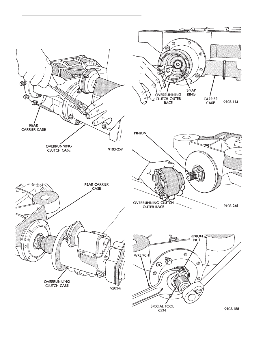
(1) Remove rear drive line module from vehicle.
(2) Remove overrunning clutch case to rear carrier

bolts (Fig. 1).

(3) Separate overrunning clutch case from differen-

tial carrier case (Fig. 2).

(4) Remove overrunning clutch outer race snap ring

(Fig. 3).

(5) Slide overrunning clutch outer race off of shaft

(Fig. 4).

(6) Using Spline Socket Tool 6534 and a wrench,

remove pinion nut (Fig. 5).

Fig. 1 Overrunning Clutch Case to Rear Carrier

Bolts

Fig. 2 Separate Cases

Fig. 3 Overrunning Clutch Snap Ring Removal

Fig. 4 Overrunning Clutch Outer Race Removal

Fig. 5 Remove Pinion Nut

.

REAR SUSPENSION AND DRIVELINE

3 - 19

(7) Remove front carrier cover retaining screws (Fig.

6)

(8) Remove front carrier cover from carrier case (Fig.

7).

(9) Place a block of wood under the end of the pinion

shaft. Tap end of pinion against the wood to drive the
pinion spacer off of the pinion shaft (Fig. 8).

CAUTION: Shim should be installed with front carrier
cover. This will eliminate the potential of cutting the
O-Ring with the shim.

(10) Reinstall front carrier cover into carrier case

(Fig. 9). Install carrier retaining bolts and tighten to 12
N

Im (105 in. lbs.).

(11) Use seal puller 7794-A (Fig. 10) to remove the

overrunning clutch seal and drive pinion seal. The
overrunning clutch seal must be removed first to gain
access to the drive pinion seal. The overrunning clutch
seal must be replaced after the drive pinion seal is
installed, do not reuse old seal.

Fig. 6 Front Carrier Cover Retaining Screws

Fig. 7 Front Carrier Cover

Fig. 8 Removing Drive Pinion Spacer

Fig. 9 Reinstalling Front Carrier Cover

3 - 20

REAR SUSPENSION AND DRIVELINE

.

INSTALLATION

(1) Clean and inspect seal area.
(2) Apply a light coat of oil onto the drive pinion seal

and install with Seal Installer 6507. Seal must be
installed with the spring side in towards the rear
carrier case (Fig 11).

CAUTION: If the drive pinion spacer is grooved or
damaged it must be replaced. A new drive pinion
bearing shim may be required. Refer to Drive Pinion
Bearing Shim Selection in this section before con-
tinuing with this procedure.

(3) Apply a light coat of oil onto the drive pinion

spacer and slide onto the pinion shaft with the tapered
side facing outward (Fig. 12).

(4) Apply a light coat of oil onto the overrunning

clutch seal and install with Seal Installer 6508 . Seal
must be installed with the spring side away from the
rear carrier case (Fig. 13).

(5) Clean pinion nut and pinion shaft threads with

Mopar

t Brake and Parts Cleaner, Loctite Cleaning

Primer or equivalent.

(6) Apply Mopar

t Lock and Seal Adhesive to both

the pinion nut and pinion shaft threads.

(7) Install pinion and tighten nut to 340 N

Im (250 ft.

lbs.) torque.

(8) Wipe off all excess adhesive.
(9) Install overrunning clutch outer race and snap

ring.

(10) Apply Loctite sealer to overrunning clutch seal-

ing surface and reinstall the overrunning clutch case to
rear carrier case.

(11) Reinstall rear drive line module assembly into

the vehicle.

(12) Check and fill all fluids as required.

Fig. 10 Removing Seals

Fig. 11 Input Seal Installation

Fig. 12 Installing Drive Pinion Spacer onto Pinion

Fig. 13 Overrunning Clutch Seal Installation

.

REAR SUSPENSION AND DRIVELINE

3 - 21

DRIVE PINION BEARING SHIM SELECTION

This procedure must be performed when ever the

drive pinion spacer has been replaced.

(1) Using a one inch micrometer, measure the thick-

ness of the original spacer (Fig. 14).

(2) Measure the thickness of the new spacer the

same way that the original spacer was measured.

The difference in the measurements of the old spacer

and the new spacer will determine which shim to use.

If the new drive pinion spacer is the same thickness

as the original drive pinion spacer use the original
shim.

If the new drive pinion spacer is thinner than the

original drive pinion spacer, a thicker shim will must
be used. This will compensate for the difference in size.

(a) Determine the difference in size between the

new spacer and the original spacer. Record this
dimension.

(b) Measure the thickness of the original shim.

Record this dimension.

(c) Add together the two dimensions recorded in

steps (a) and (b). Use a new shim that is equal to this
size.
For Example: The new spacer is 0.010 thinner than

the original spacer. The original shim measures 0.205 .
Adding 0.205 and 0.010 equals a new shim thickness of
0.215 .

(3) If the new drive pinion spacer is thicker than the

original drive pinion spacer, a thinner shim will must
be used. This will compensate for the difference in size.

(a) Determine the difference in size between the

new spacer and the original spacer. Record this
dimension.

(b) Measure the thickness of the original shim.

Record this dimension.

(c) Subtract the dimensions recorded in steps (a)

from the dimension recorded in step (b). Use a new
shim that is equal to this size.
For Example: The new spacer is 0.010 thicker than

the original spacer. The original shim measures 0.205 .
Subtracting 0.010 from 0.205 equals a new shim thick-
ness of 0.195 .

REAR DRIVELINE MODULE DIFFERENTIAL SIDE
GEARS

(1) Disconnect both half shafts from rear driveline

module.

(2) Using two pry bars, pop out output shaft.
(3) Remove output shaft.
(4) Remove end cover retaining bolts.
(5) Remove differential end cover.
(6) Remove differential assembly from rear driveline

case.

(7) Remove ring gear bolts and separate differential

case from differential body.

(8) Using a punch and hammer remove the differen-

tial pinion shaft pin.

(9) Slide differential pinion shaft out of differential

case.

(10) Inspect and replace pinion gears, pinion shaft or

pinion washers as required.

(11) Reverse steps 7 through 10 to assemble differ-

ential. Torque the ring gear bolts to 95 N

Im (70 ft. lbs.).

(12) Install differential assembly into driveline mod-

ule case.

(13) Clean and inspect sealer surfaces.
(14) Apply Mopar

t Gasket Maker, Loctite Gasket

Eliminator or equivalent and install end cover. Tighten
to 28 N

Im (250 in. lbs.).

(15) Tighten bolts in the sequence shown in Fig. 15.

Retighten first bolt after all others are tight.

(16) Install output shafts
(17) Reconnect both half shafts.
(18) Fill differential with lubricant.

Fig. 14 Measuring Drive Pinion Spacer Thickness

3 - 22

REAR SUSPENSION AND DRIVELINE

.


Content   ..  146  147  148  149   ..