Chrysler Town & Country/Voyager, Dodge Caravan, Plymouth Voyager. Manual - part 56


  Index      Chrysler     Chrysler Town & Country/Voyager, Dodge Caravan, Plymouth Voyager - service repair manual 1992 year


Search            


Content   ..  54  55  56  57   ..


Chrysler Town & Country/Voyager, Dodge Caravan, Plymouth Voyager. Manual - part 56


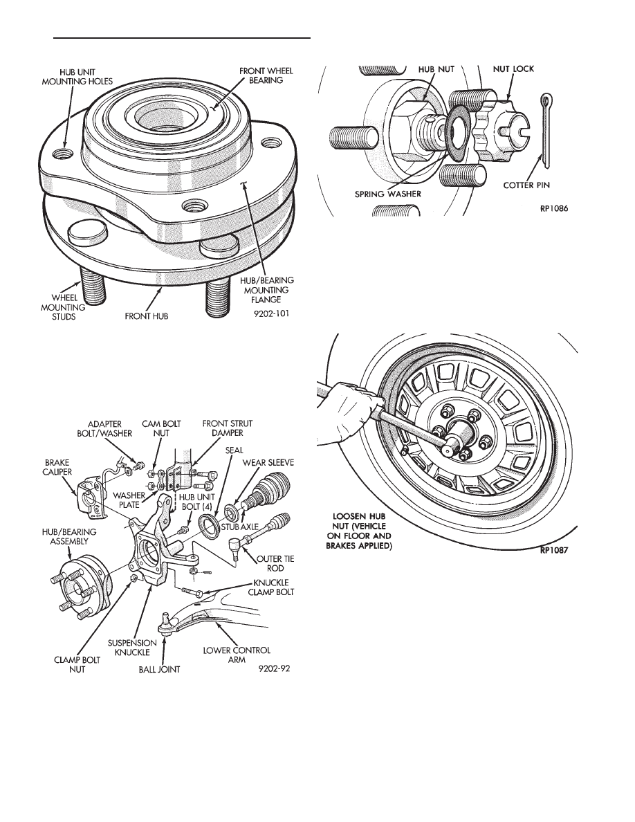
This unit is serviced only as a complete assembly

(Fig. 1). It is mounted to the steering knuckle by four
mounting bolts that are removed from the rear of the
steering knuckle (Fig. 2).

REMOVAL

Replacement of the front (drive) hub and bearing

assembly can be done without having to remove the
steering knuckle from the vehicle.

(1) Remove cotter pin, hub nut lock, and spring

washer (Fig. 3).

(2) Loosen hub nut while the vehicle is on the floor

with the brakes applied (Fig. 4). The hub and drive-
shaft are splined together through the knuckle
(bearing assembly) and retained by the hub nut.

(3) Raise vehicle, see Hoisting Recommendations in

Group 0 of this service manual.

(4) Remove the hub nut and the washer from the

stub axle (Fig. 3).

(5) Remove the wheel lug nuts, and tire and wheel

assembly from the vehicle.

Fig. 1 Unit III Front Hub And Bearing Assembly

Fig. 2 Front Hub And Bearing Assembly Mounting

Fig. 3 Remove Cotter Pin, Nut Lock, & Spring

Washer

Fig. 4 Loosen Hub Nut

.

FRONT SUSPENSION AND DRIVE SHAFTS

2 - 21

(6) Disconnect tie rod end from steering arm with

Puller Special, Tool C-3894-A (Fig. 5).

(7) Remove clamp bolt securing the ball joint stud

into the steering knuckle (Fig. 6).

(8) Remove caliper guide pin bolts (Fig. 6) and sepa-

rate caliper assembly from braking disc. Support

caliper with wire hook and not by hydraulic
hose. 
(Fig. 7) Remove braking disc from hub and
bearing assembly (Fig. 8).

(9) Separate the steering knuckle assembly from the

ball joint stud. Pull knuckle assembly out and away
from driveshaft (Fig. 9).

Care must be taken not to separate the inner

C/V joint during this operation. Do not allow
driveshaft to hang by inner C/V joint, driveshaft
must be supported.

(10) Remove the four hub and bearing assembly

mounting bolts from rear of steering knuckle (Fig. 9).

Fig. 5 Disconnect Tie Rod End

Fig. 6 Remove Clamp Bolt and Caliper Guide Pins

Fig. 7 Supporting Brake Caliper

Fig. 8 Remove or Install Braking Disc

2 - 22

FRONT SUSPENSION AND DRIVE SHAFTS

.

(11) Remove the hub and bearing assembly from the

steering knuckle (Fig. 10). Replacement of the
grease seal is recommended whenever this ser-
vice is performed.

INSTALLATION

CAUTION: All steering knuckle and bearing mounting
surfaces must be smooth and completely free of
foreign material or nicks.

(1) Install new front hub and bearing assembly into

the steering knuckle. Tighten the hub and bearing
assembly to steering knuckle attaching bolts (Fig. 9), in
a criss-cross pattern to 65 N

Im (45 ft. lbs.) torque.

(2) Position new hub and bearing assembly seal in

recess of the steering knuckle (Fig. 11). Assemble
Installer, Special Tool C-4698. Tool is provided with a
handle and dual purpose drive head for installing seal
into knuckle and (head reversed) for installing wear
sleeve onto C/V joint housing.

(3) Using Special Tool C-4698 (Fig. 11) install the

hub and bearing seal, until fully seated into the steer-
ing knuckle recess.

CAUTION: During any service procedures where

knuckle and driveshaft are separated, thoroughly
clean seal and wear sleeve and lubricate BOTH com-
ponents.

Fig. 9 Separate Ball Joint Stud from Steering

Knuckle

Fig. 10 Separate Hub and Bearing Assembly from

Knuckle

Fig. 11 Bearing Seal Installation

.

FRONT SUSPENSION AND DRIVE SHAFTS

2 - 23

(4) Lubricate the FULL circumference of the bearing seal

(and wear sleeve) as shown in (Fig. 12). With Mopar

t

Multi-Purpose Lubricant, or equivalent.

(5) Insert driveshaft through hub and bearing as-

sembly, while installing steering knuckle assembly on
lower control arm ball joint stud (Fig. 13).

(6) Install original (or equivalent) ball joint to

knuckle clamp bolt (Fig. 14) into steering knuckle.
Tighten clamp bolt to 136 N

Im (100 ft. lbs.) torque.

(7) Install tie rod end into steering knuckle arm (Fig.

15). Tighten tie rod to steering knuckle arm attaching
nut to 47 N

Im (35 ft. lbs.) torque and install cotter pin.

(8) Install braking disc (Fig. 8).

(9) Carefully lower brake caliper assembly over

braking disc (Fig. 16).

(10) Install brake caliper assembly guide pin bolts.

Tighten guide pin bolts to 25-35 N

Im (18-26 ft. lbs.)

torque. When installing guide pins, use extreme
caution not to cross the threads.

Fig. 12 Seal and Wear Sleeve Lubrication

Fig. 13 Installing Knuckle Assembly

Fig. 14 Tighten Clamp Bolt

Fig. 15 Install Tie Rod End

2 - 24

FRONT SUSPENSION AND DRIVE SHAFTS

.


Content   ..  54  55  56  57   ..