Chery QQ6 (Chassis). Service Manual - part 2
 

  Index      Chery     Chery QQ6 (Chassis). Service Manual


Search            copyright infringement  


Content      ..      1      2      3      ..


Chery QQ6 (Chassis). Service Manual - part 2


17 

4.4 Remove the hand brake control cable at the other side   

with the same method.   


4.5 Remove two fixing bolts from the driver’s seat with a   

16# socket wrench, and then take off the seat.   


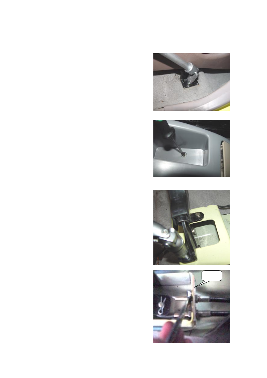
4. 6 Remove all fix screws from the auxiliary instrument 

panel assy with a cross screwdriver, and then take off the   

auxiliary instrument panel assy. 


4.7 Remove two hand brake fixing bolts as shown in the 

picture with a 10# socket wrench. 


4.8 Loosen two control cable fixing screws with a 14# box 

Wrench, and then take off the guide plate. 


Guide 
Plate 

-------------------------------------------------------------------------------------------------------------------------------------------------------------

18 

4.9 Remove the pin clip with a screwdriver   


4.10 Take off the control cable take-up pulley.   


4.11 Draw out the hand brake control cable from the 

bottom of vehicle body. 


4.11 (Adjustement of hand brake) The design length of 

this vehicle’s hand brake control cable is fixed. Refer to the 

rear brake removal step for the adjustment of hand brake.   

Adjusting the length of jogger (loosening it in clockwire 

direction; tightening it in anticlockwise direction) can   

implement the adjustment of hand brake. 


4.12 Refer to the removel step for the installation step. 


Turn Hear 

-------------------------------------------------------------------------------------------------------------------------------------------------------------

19 


Chapter 2    Adjustment of Suspension System and 

Four-Wheel Alignment System 

I. Disassembly, Reassembly and Maintenance of Front Axle and 

Suspension System 

1. Structural Diagram of System 

The CHERY S21 car adopts the  divided steering  drive axle, with a McPherson  independent 

suspension.  The  upper  of  the  suspension  connects  to  the  body  while  the  lower  to  the  subframe. 

The McPherson independent suspension bears the drive and steering functions. Subframe connects 

with vehicle body via elastic element, which improves diving stability and ride comfortability. 


Structural diagram of Front Axle and Suspension System 


-------------------------------------------------------------------------------------------------------------------------------------------------------------

20 

Details of Front Axle and Suspension System Composition Diagram 


1  Nut 

Nut 

17 

Nut 

2  Gasket 

10 

Left Control Arm 

18 

Nut 

3  Rubber joint I 

10 

Right Control Arm 

19 

Bolt 

4  Rubber joint II 

11 

Nut 

20 

Bolt 

5  Left Push Rod Welding Assy 

12 

Subframe 

21 

Clamp 

5  Right Push Rod Welding Assy  13  Front Strut Assy. 

22 

Rubber Bush 

6  Nut 

14 

Nut 

23 

Bolt 

7  Bolt 

15 

Front Connecting Rod Assy. 

24 

Bolt 

8  Bolt 

16 

Front Stabilizer Bar 

25 

Bolt 


-------------------------------------------------------------------------------------------------------------------------------------------------------------

21 

2. Preparation 

Tools: 8#, 15#, 18#, 19# sleeves; 10#, 13#, 15# wrenches.   


3. Precautions 

3.1 Please wear necessary labor protection supplies to avoid accidents. 

3.2 Please attention whether the safety lock of lifter is locked when maintaining the chassis. 

3.3  When  carry  out  disassembly  and  assembly  to  shock  absorber  spring,  prevent  spring  ejection 

from being injured. 

3.4 It is unallowable to weld and correct the load-carrying parts of wheel suspension and the guide 

parts of wheel.   

3.5 Update the locknut and rusty nuts  when the chassis parts are removed, which the objective is 

to ensure the safety. 

4. Removal/Installation Step 

4.1. Removal of shock absorber assy 

4.1.1 Remove the tightening nuts from the tires with a 19# sleeve   

or attached wrench, and then remove the tires (Left side as an   

example).   

Torque: 110±10N.m 


4.1.2 Take off the ABS harness from the fixed seat by hand.   


4.1.3 Remove the fixing bolts from the steering knuckle and shock 

absorber with a 18# sleeve. 

Torque: 110±10 N.m 


-------------------------------------------------------------------------------------------------------------------------------------------------------------

22 

4.1.4 Remove three fixing bolts to the frame from the shock   

absorber assy with a 15# sleeve. 

Torque: 60±5N.m 


4.1.5 Remove the shock absorber assy. 


4.2. Removal of control arm assy 

4.2.1 Remove the fixing bolts to the control arm from the front   

connecting rod assy with a 15# sleeve. 

Torque: 100±10 N.m 


4.2.2 Remove the connecting bolts of front push bar and control   

arm with a 15# wrench.   

Torque: 75±5 N.m 


4.2.3 Remove the ball bolts from the control arm and steering   

universal joint assy with a 18# sleeve.   

Torque: 100±10N.m   


4.2.4 Remove the connecting bolts from the control arm and front   

axle with a 18# sleeve, and then take off the control arm assy.   

Torque: 150±10 N.m 


-------------------------------------------------------------------------------------------------------------------------------------------------------------

23 

4.3. Removal of front axle 

4.3.1 Remove the fixing bolts from the mud guard of chassis with 

a 8# sleeve, and then take off the mud guard assy. 

Torque: 3±0.5 N.m 


4.3.2 Remove the front bracket bolts to the subframe from the   

transmission with a 19# sleeve.   

Torque: 110±10N.m 


4.3.3 Remove the rear bracket bolts to the subframe from the 

transmission with a 19# sleeve. 

Torque: 110±10N.m 


4.3.4 Remove two connecting bolts from the exhaust manifold   

with a 15# sleeve.   

Torque: 50±5Nm. 


4.3.5 Remove two connecting bolts used to connect the exhaust   

manifold and rear muffler with a 15# sleeve. 

Torque: 50±5Nm. 


-------------------------------------------------------------------------------------------------------------------------------------------------------------

24 

4.3.6 Remove the fixing bolts from the right side of power assist 

steering wheel with a 15# wrench. 

Torque: 75±5 N.m 


4.3.7 Remove the fixing bolts from the left side of power assist   

steering wheel with a 15# wrench. 

Torque: 75±5 N.m 


4.3.8 Remove the fixing bolts used to connect the push bar and   

subframe with a 19# sleeve. 

Torque: 105±10 N.m 


4.3.9 Remove the fixed support from A/C pipeline on the subframe 

with a 10# wrench.   

Torque: 25±2.5 N.m 


4.3.10 Remove the fixed support from the condenser and subframe 

with a 13# wrench.   

Torque: 45±5 N.m 


-------------------------------------------------------------------------------------------------------------------------------------------------------------

25 


4.3.11 Remove four nuts used to connect the subframe and body with 

a 18# sleeve, and then take off the front axle assy. 

Torque: 150±10 N.m 


4.3.12 Remove the fixing bolts and nuts from gum cover of stabilizer 

rod with a 13# sleeve. 

Torque: 50±5Nm. 

5. Installation Step 

Refer to Removal Step of Front Axle and Front Suspension System


-------------------------------------------------------------------------------------------------------------------------------------------------------------

26 

II. Disassembly, Reassembly and Maintenance of Rear Axle and 

Suspension System 

1. Structural Diagram of System 


Structural diagram of Rear Axle and Suspension System 


1


Rear Trailing Arm Assy


7


Rear Shaft Welding Assy


13


Nut


2


Bolt


8


Lateral Support Bar Assy


14


Nut


3


Rear 

Shock 

Absorber 

Assy


9


Rear Spring Cushion


15


Bolt


4


Nut


10


Rear Bumper Block


16


Lock Nut


5


Bolt


11


Rear Coil Spring


17


Rear Brake With Drum Assy


6


Bolt


12


Nut


18


Bolt


-------------------------------------------------------------------------------------------------------------------------------------------------------------

27 

2. Preparation 

Tools: 11#, 13#, 15#, 18#, 19#, 30# sleeve; right-angled screwdriver;   

pincers.   

3. Precautions.   

3.1 Please wear necessary labor protection supplies to avoid accidents. 

3.2 Please attention whether the safety lock of lifter is locked when maintaining the chassis.   

3.3  When  carry  out  disassembly  and  assembly  to  shock  absorber  spring,  prevent  spring  ejection 

from being injured. 

4. Removal/Installation Step 

4.1. Removal of shock absorber assy and absorber spring 

4.1.1 Remove the tightening nuts from the tires with a 19# torque   

spanner or attached wrench, and then take off the tires (left side as   

an example).   

Torque: 110±10N.m 


4.1.2 Remove the connecting bolts from the shock absorber assy and   

rear axle with a 15# sleeve. 

Torque: 100±10 N.m 


4.1.3 Remove the connecting bolts of the shock absorber assy and   

body with a 18# non-adjustable wrench, and then take off the shock 

absorber assy. 

Torque: 100±10 N.m 


-------------------------------------------------------------------------------------------------------------------------------------------------------------

28 

4.1.4 Unclench the rear helical spring with a screwdriver.   


4.1.5 Forcefully swing leftwards and rightwards the rear   

bumper block by hand and then take off the block.   


4.2. Removal of lateral support bar assy 

4.2.1 Remove the connecting bolts from the left side of body   

and lateral support bar with a 15# sleeve.   

Torque: 100±10N.m   


4.2.2 Remove the connecting bolts from the right side of body   

and lateral support bar with a 15# sleeve, and then take off the   

lateral support bar assy. 

Torque: 100±10N.m 


4.3. Removal of rear trailing arm assy 

4.3.1 Remove the connecting bolts from the rear of rear axle   

and trailing arm assy with a 13# sleeve. 

Torque: 100±10N.m 


-------------------------------------------------------------------------------------------------------------------------------------------------------------

29 

4.3.2 Remove the connecting bolts from the intermediate of rear 

  axle and trailing arm assy with a 13# sleeve. 

Torque: 100±10N.m 


4.3.3 Remove the connecting bolts from the trailing arm and   

body with a 15# wrench, and then take off the rear trailing   

arm assy.   

Torque: 100±10N.m 


4.4. Removal of rear axle assy 

4.4.1 Remove the connecting bolts from the brake pipeline   

and rear axle with a 11# wrench. Attention to storage of brake   

fluid. 

Torque: 45±5 N.m 


4.4.2 Remove the rear brake with drum assy by hand.   


4.4.3 Remove the hand brake control cable with a plier.   


-------------------------------------------------------------------------------------------------------------------------------------------------------------

30 

4.4.4 Remove the lock nuts from the rear brake with drum   

assywith a 30# combination sleeve, and then take off the rear   

brake with drum assy.   

Torque: 180±10N.m 


4.4.5 Remove the rear axle assy.   


5. Installation Step 

The installation step is reverse to that of removal. 


-------------------------------------------------------------------------------------------------------------------------------------------------------------

31 

III. Adjustment of Four-Wheel Alignment System 

Please  check  and  adjust  the  parameters  with  the  help  of  the  four-wheel  alignment  system 

recommended by the CHERY Automobile Co.. Ltd.   

S21 standard four-wheel alignment system parameters:   

Item 

Parameter 

Model 

SQR7130S21 

SQR7110S21 

Front Wheel 

Camber Angle 

0.87°±50′ 

0.87°±50′ 

Kingpin Caster 

Angle 

3.4°±30′ 

3.4°±30′ 

Kingpin 

Inclination Angle 

12.7° 

12.7° 

Front 

Wheel 

Front Wheel 

Toe-In 

6′±6′ 

6′±6′ 

Rear Wheel 

Camber Angle 

0°±30′ 

0°±30′ 

Rear 

Wheel 

Rear Wheel 

Toe-In 

0°±10′ 

0°±10′ 

Sideslip   

≤ 3m/km 

≤ 3m/km 


1. Adjustment of Front Wheel Toe-In 

The toe-in can be adjusted using an optical tester or a mechanical toe-in regulator.   
1.1  On  the  basis  of  requirement  of  the  tester,  position  the  wheels  and  conduct  the  preparation 
work before adjusting. 
1.2 Loosen the lock  nut and  of the  elastic  protective sleeve snap ring right steering tie bar. Turn 
the toe-in regulator lever as required to regulate the length until it reaches the specified value; and 
the toe-in value: 6′±6′. 
1.3  Tighten  the  lock  nut,  reinstall  the  elastic  snap  ring  of  protective  sleeve,  and  then  check 
whether the lock nut is tightened and whether the position of protective sleeve is proper;   
Torque: 35±3Nm 
1.4 After adjusting toe-in of front wheel, check whether the steering wheel is horizontal. 
Otherwise,  loosen  the  lock  nut  of  steering  wheel,  regulate  the  steering  wheel  to  the  horizontal 
position, and then tighten the steering wheel lock nut to the specified torque. 

2. Adjustment of Front Wheel Camber Angle 

2.1 In the normal case, after the independent suspension and   

wheel steering knuckle are assembled, it is unnecessary to   

adjust the camber angle. If the wheel camber angle is found   

deviated from the tolerance range due to the other causes,   

apply the connecting bolts of independent suspension and   

steering knuckle to correct the camber angle.:   

Front wheel camber angle: 0.87°±50′ 


-------------------------------------------------------------------------------------------------------------------------------------------------------------

32 

2.2  Before  correction,  check  (visually)  whether  the  parts  of  running  system  is  damaged,  and 

repalce the damaged parts;   


2.3 If the  front  wheel  camber angle is found  out  of the  tolerance range, loosen the connecting 

bolts of front shock absorber and steering knuckle, and move the wheel to correct the angle. 

3. Adjustment of Kingpin caster and inclination angles 

The  Kingpin  caster  and  inclination  angles  are  guaranteed  by  the  design  structure,  without 

adjustment in service. The Kingpin caster angle: 3.4°±30′, Kingpin inclination angle: 12.7°. If any 

parameter exceeds the specified range, replace thesteering knuckle only. 

4. Adjustment of rear wheel positional parameters 

All of the rear wheel alignment parameters shall be guaranteed through design process. 

4.1 Rear wheel camber angle: 0°±30′


4.2 Rear wheel toe-in: 0°±10′ 

4.3  If  the  rear  wheel  alignment  parameters  change  due  to  the  deformation  of  rear  axle  which  is 

subject  to  the  very  big  impact  force,  and  these  parameters  exceed  the  specified  range,  correct  or 

replace the rear axle only.   

IV. Installation of Tire and Regulation of Air Pressure 

1.    Assembly of Tire Valve   

Prior to the assembly of tire valve, firstly check the valve port to ensure whether it is smooth and 

free  from  burr,  and  then  apply  glycerol  on  the  rubber  body  surface,  or  soak  the  tire  valve  into 

glycerol. Pull or press using special tools with 200 - 400N to make the locating ring of the valve 

can go through the wheel  holes, to this  point, the assembly is completed (soap water is allowed 

to substitute glycerol). 

2. Assembly of Tire 

Before assembly of the tire, apply glycerol or soap water along the cycle of tire bead, meanwhile, 

note that: 

2.1 If the wheel rim has the dot marks, align the uniformity testing marks with the dot marks of 

the wheel rim.   

2.2 When without dot marks on the wheel rim, align the dynamic balance testing mark of tire to 

valve position. 

2.3 When without dot marks on the wheel rim, additionally, there is no dynamic balance testing 

mark,  however,  static  balance  testing  mark  is  available,  align  the  valve  to  the  static  balance 

testing mark. 

2.4 The description concerning the uniformity, dynamic balance and static balance testing marks 

-------------------------------------------------------------------------------------------------------------------------------------------------------------


Content      ..      1      2      3      ..