Chery QQ3. Service Manual - part 5
 

  Index      Chery     Chery QQ3. Service Manual


Search            copyright infringement  


Content      ..     3      4      5      6     ..


Chery QQ3. Service Manual - part 5


Instruments and control devices 

56 

the fluid level is low, refill the specified 

brake fluid. 2. check whether the brake 
works normally or not. 3.  slowly drive 
your vehicle to the M aintenance Center to 

have it checked if the brakes work 
normally.  4.  drag your vehicle to the 
Chery Authorized Service Station  if the 

alarm indicator lamp lights for a long 
time and any brake works abnormally or 
the brake fluid is found leakage.   

The too low brake fluid level may 
lengthen the braking distance, and also 
increase the brake force and p edal travel.   

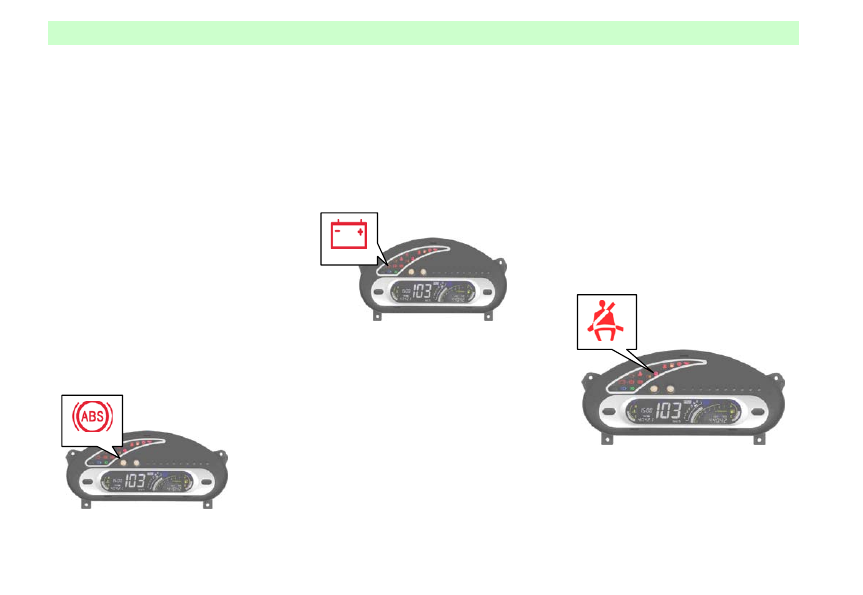
ABS  alarm indicator lamp (for 
the models equipped with the 
ABS)


The indicator lamp lights after turning on 
the  ignition switch, and, waiting  for 
approx. 4 s, then extinguishes. 
If the indicator lamp doesn’t light after 
turning on the ignition switch, or the 
lamp doesn’t extinguish after it lights, 
please cont act the nearest Chery 
Authorized Service Station.   


If this indicator lamp lights when the 

vehicle is traveling, it illustrates that the 
ABS has trouble(s). Without the ABS 
function, the vehicle’s brake system still 
works as usual. However, in this case, 
you shall get to the nearest Chery 
Authorized Service Station  to have your 
vehicle checked.  
 

Generator alarm indicator lamp


This alarm ind icator lamp indicates that 
the battery is discharging.   
The indicator lamp lights when the 
ignition switch is turned  on, and 
extinguishes after the engine starts up. 
If the indicator lamp lights when the 
vehicle is traveling, you shall 

● park your vehicle on the roadside; 

●  check  whether  the belt of generator is 
slack or broken 

● find out the trouble ASAP and remove 
it if the belt is in good condition and the 
charging system may be in trouble, and 
immediately get to the nearest Chery 
Authorized Service Station  to have the 

charging system checked.   
!CAUTION 
The too loose generator belt may result 
that  the engine is overheat. It may 
damage the engine. So, regularly check 
the generator belt. 

Seat belt alarm indicator lamp


In case that the ignition switch is placed 
to the position “Ⅱ”

, unless the driver has  

put on the seat belt, the seat belt alarm 
indicator lamp will light.   


-------------------------------------------------------------------------------------------------------------------------------------------------------------

Instruments and control devices 

57 

Airbag alarm indicator lamp (for 
the  models equipped with the air 
bag)


The indicator lamp lights  after turning on the 
ignition switch, and, waiting for approx. 4 s, then 
extinguishes. It illustrates that the airbag system is 
normal. 
If the indicator lamp do esn’t light or the lamp 
doesn’t extinguish after it lights for 4 s, or blinks 
continuously and even lights for a long time when 
the vehicle is traveling, it indicates that the airbag  
system has trouble(s). In the case o f troubl e, the 
airbag system fails to be activated,  please 
immediately cont act the nearest Chery Authorized  
Service Station  to have it checked.  If the airbag 
system can’t be repaired in time, it can’t  play its 
proper role after the serious compact occurs. Any 
damage or injure caused h erein is exclusive in the 
warranty. 

Transmission trouble alarm 
indicator lamp (for the models 
with the AMT transmission

)


The indicator lamp lights after turning on 
the  ignition switch, and, waiting for 
approx. 4 s, then extinguishes. 
If the indicator lamp doesn’t light after 
turning on the ignition switch, or the 
lamp doesn’t extinguish after it lights, 
please cont act the nearest Chery 
Authorized Service Station. 

Transmission oil temperature & 
trouble alarm indicator lamp (for 
the models with the AMT 
transmission

)


  The indicator lamp lights after turning 
on the  ignition switch, and, waiting for 
approx. 4 s, then extinguishes. 
If the indicator lamp doesn’t light after 
turning on the ignition switch, or the 
lamp doesn’t extinguish after it lights, 
please cont act the nearest Chery 
Authorized Service Station. 

Gearshift display (for the models 
with the AMT transmission

)


The position of gear selection lever will 
be displayed on the display located at the 
center of the instrument panel after 
turning on the ignition switch. It will 
display the position of each gearshift in 
the column-shaped form. 


-------------------------------------------------------------------------------------------------------------------------------------------------------------

Instruments and control devices 

58 


Manual mode: 

In the manual gear shift mode, the 
gearshift selected by the  driver will be 
displayed on the display in the 
column-shaped form.   

Automatic mode: 

Press the “AUTO”  button to enter the 
automatic gear shift mode. In this case, 
the  “AUTO”  indicator in the instrument 
panel will light, and the current gearshift 
will be displayed on the display in the 
column-shaped form.   

Turn signal indicator lamp/hazard 
alarm flash indicator lamp


When turn on the turn lamp switch or 
hazard alarm lamp switch, their indicator 
lamp flash, which ind icates  that the 
external turn signal lamp or hazard alarm 
lamp is working. The high flash 
frequency shows that the turn signal lamp 
bulb has trouble.   

!CAUTION 

If the bulb is burnt out, immediately 
replace it to avoid the occurrence of 
accident. If the green arrow doesn’t light 
when the turn signal is sent out, please 
check whether the fuse and bulb are burnt 
out.   

High beam indicator lamp


Turn on the high beam, this indicator 
lamp will light.   


Front/Rear fog lamp switch


The 1

st

The 2

  gear is used to turn on the front fog 

lamp. 

nd

When the switch is placed  to the 2

  gear is used to turn on the front and 

rear  fog  lamps, or turn on the rear  fog  lamp 
only.   

nd

After the ignition switch is turned on, the front 
fog lamp will work only after the position 
lamp  is turned on, and  can  work together  with 
the high beam or low beam. The rear fog lamp 
can work only with the front fog lamp at the 
same time.   

  gear 

position, the indicator lamp on the switch will 
light.   

Since the glare of the rear fog lamp is 
strong, the rear fog lamp is allowed to be 
used only in the case of low visibility 

Gearshi ft display  


-------------------------------------------------------------------------------------------------------------------------------------------------------------

Instruments and control devices 

59 

(below 50 m).   


How to operate these instruments 

TRIP  A, TRIP B and  Traveling Time 
switchover, display and reset   
The function of “TRIP” button is to select 

the display mode of  “TRIP”  and 
“Traveling Time”.  Its specific op eration 
procedure is as follows: 
 
1.  The initial display is TRIP A. If the 
TRIP A is 1,357.9 km, the TRIP display 
shows: 


2.  Press the “TRIP”  button once, the 
TRIP A is switched to the TRIP B. In this 
case, if the TRIP B is  2,468.0  km, the 
TRIP display shows:   


3.  Press the “TRIP”  button again, the 
TRIP B changes to the Traveling Time. In 
this case, if the traveling time is: 1h 35m, 
it will be displayed as: 


4.  In case of TRIP A, TRIP B or 

Traveling Time, press the button for 
above 2 s to reset.   
——Description: 
(1) These two TRIPs can be 
independently applied. For instance, the 
TRIP A can be used to record the total 
mileage each a tank of  fuel, and  the TRIP 
B to record the mileage each out going 
travel.   
(2) The Traveling Time is designated to 
display the time counted from the startup 
of engine. For example, in accordance 
with  the  operation procedure above, the 
display is turned to “Traveling Time” 
mode during the vehicle is driving. In this 
case, if the time is displayed as 3-25, it 
illustrates that the vehicle has traveled 
continuously for 3 hours and 25 minutes. 
Apart from the manual reset, this timer 
also begins to count from 0-00 when the 
engine restarts.   

● Temporary adjustment of brightness 
of the display
   
In case that the instrument lights, press 
the “SEL” key to adjust the brightness of 
the display. The brightness adjustment is 
divided into 10 levels each a cycle. The 
brightness level increments if you press 
the key once. When the brightness 
reaches its maximum value, press the key 


-------------------------------------------------------------------------------------------------------------------------------------------------------------

Instruments and control devices 

60 

once, and then the brightness level will 
return back to the minimum value.   

● Clock’s integral point calibration 
In case that the clock displayed is within 
the integral point to or past 2 minutes, 
press the “TRIP”  and  “SEL”  buttons at 
the same time to calibrate  the integral 
point of the clock. For instance: When the 
time displayed  is  14:59  but the actual 
time is just 15:  00, this calibration 
op eration can immediately calibr ate the 
clock to 15:00. 

● Setting   
The following functions can be 
implemented only after entering the 
setting status.   

 Enter the setting status   
Press the key “SEL” for 2 s to enter the 
setting status. In this case, the  “SET” 
mark on the odometer flashes, which 
indicates that the  instrument has entered 
into the setting status.   

● Exit from the setting status 
In case of setting status, if press the key 
“SEL” for 2 s or 15 s and do not carry out 
any other operation, the instrument exits 
from the setting status and the mark 
“SET” extinguishes.   
1. Clock initialization 

In case that the mark “SET”  flashes, 
simultaneously press the “SEL”  and  
“TRIP”  buttons once for a short time to 
enter the clock initialization mode. In this 
case, the Hour digital flashes. Press the 
“TRIP” button to adjust the value of Hour 
digital, with the increment every a press. 
If press the “TRIP”  button and keep it, 
the Hour digital increases automatically 
till the Hour digital is right; if it is 
unnecessary to adjust the Hour value, 
directly press the “SEL”  button to enter 
the M inute adjustment status. In this case, 
the Min digital flashes. Press the “TRIP” 
button to adjust the value of M in digital, 
with the increment every a press. If press 
the  “TRIP”  button and keep it, the M in 
digital increases automatically till the 
M in digital is right. 
After the completion of adjustment, 
simultaneously press the “SEL”  and  
“TRIP”  buttons for a short time to 
complete the clock setting. 
1. Daytime display brightness setting 
Press the “SEL”  button to enter the 
setting status. The SET code is displayed 
as follows: 


It means that in the case of “Daytime 
Display Brightness” setting status, the left 
two digitals represent the daytime 
brightness  setting status mark while the 
right three digitals represent the set value 
which can be selected from 1 to 100 and 
the initial value is max. 100. Press the 
“TRIP” button once to decrease the value 
by 10. For  instance: To adjust the 
brightness to 85, its operation procedure 
is as follows: Press the “TRIP” button t ill 
the value displayed is 90, and then release 
the button and  press the “TRIP”  button 
five times to get the brightness of 85.   
2. 

Nighttime display brightness 

adjustment 
  Press the “SEL”  button to enter the 
setting status. The SET code is displayed 
as follows: 


-------------------------------------------------------------------------------------------------------------------------------------------------------------

Instruments and control devices 

61 

It means that in the case of “Nighttime 
Display Brightness” setting status, the left 
two digitals represent the nighttime 
brightness  setting status mark while the 
right three digitals represent the set value 
which can be selected from 1 to 100 and 
the initial value is min. 001. Press the 
“TRIP” button once to increase the value 
by 1, and press the “TRIP”  button and 
keep it, the value will automatically 
increase by 10. For instance: To adjust 
the brightness to 35, its operation 
procedure is as follows: Press the “TRIP” 
button till the value displayed is 30, and 
then release the button and  press the 
“TRIP”  button five times to get the 
brightness of 35. 
 
3. Nighttime display brightness control 

priority setting   

Select any  one of the following cases: the 
brightness  adjustment  knob has priority 
over the setting or vice versa. The initial 
default is that the brightness adjustment 
knob control has the priority.   
Press the “SEL”  button to enter the 
“Nighttime Display Brightness Control 
Priority” setting. And it is displayed as: 


In this case, it presents the brightness 
adjustment knob control priority status. 
Press the “TRIP”  button once. And it is 
displayed as:   


In this case, it presents the instrument 
internal setting priority status.   
4. Service mileage setting 
Press the “SEL”  button to enter the 
“Service M ileage” setting. It is displayed 
as: 


The left one digital presents that the 
instrument is in the Service M ileage 
setting status while the right four digitals  
present the  set value of mileage which 
can be selected from 100 to 9,900 km. Its 
initial value is 0000 which means that it 

is not set yet. Press the “TRIP”  button 
once to increase the value by  100, and 
press the “TRIP” button and keep it, the 
mileage value will automatically increase 
by 1,000. For example: To set the service 
mileage to 7,500  km, its operation 
procedure is as follows: Press the “TRIP” 
button till the value displayed is 7,000 
and then release the button, and press the 
“TRIP”  button five times to get the 
service mileage of 7,500 km.   
When the vehicle travels 7,400 km, 7,450 
km  and  7,  500  km  respectively, the 
odometer will display respectively as 
follows: 


-------------------------------------------------------------------------------------------------------------------------------------------------------------

Instruments and control devices 

62 


It shows that the mileages remained from 
the service mileage set are  100  km,  50 
km and 0 km respectively. Each reminder 
is accompanied by the beep sound, with 
the duration of 10 s.   

●  Status or initial  value of the 
instruments re-powered after power off   
Both the positive  input of power supply 
and the positive input of ignition switch 
POWER OFF, and the relevant data of 
the instruments will be lost after 
re-powered on. The related initial values  
of common instruments can be restored 
as follows: 
⒈ Clock display: 00:00 

⒉ Traveling time: 00-00 
⒊  Service mileage: 0, it is required to 
reset. 
⒋  Brightness value: Daytime----100; 
Nighttime----1. 
⒌  Brightness control mode: The default 

mode is knob-operated control.   


Turn signal light switch 

Turn signal lights may work only when 
ignition switch is turned on. A right turn 
will be signaled when turn signal light 
switch is moved up.  A left turn will be 
signaled when turn signal light switch is 

moved down.  Turn signal lights will go 
out after turn and turn switch returns to 
normal position. 
When driveway shift is made ,move 
switch not completely (without finishing 
full travel) and hold on it. Turn signal 
light switch will return to its normal 
position after released. 


Headlight high beam 

switch 

With headlight low beam on, headlight 
high beam will be turned on when control 

lever is pushed towards dashboard and 
high beam indicator light will light up 
simultaneously. 
Headlight low beam will be lit up  when 
control lever is pushed back to original 
position. 
 
Notice 
Here, headlight switch must stay 

"

" position all the time. 


-------------------------------------------------------------------------------------------------------------------------------------------------------------

Instruments and control devices 

63 

Passing light switch 

Headlight high beam will come on if 
control lever is turned towards steering 
wheel, then cont rol lever may be released.  
Control lever will return to normal 
position after released.  Headlight high 
beam will remain on when control lever 
is hold on by driver. 


Windshield wiper switch 

 
With ignition switch turned on, 
windshield wiper may be operated when 
control lever is turned upward. 
OFF=stop. 
INT=intermittent wiping (with a interval 
of 4 seconds) 
LOW= continuous wiping, low speed 

HIGH= continuous wiping, high speed 

Fuzzy function 

If driver turn control lever to INT 
position lightly and release it, wiper will 
op erate once. Wiper will work once after 
control lever return to normal position 
automatically.  
 
Notice 
If wiper blades are worn, which will 
cause a improper wiping affecting front 
sight, wiper blades should be replaced. 
With no water, wiper's operation will 
scrape glass resulting in premature 
deterioration of wiper blades and 
disturbing driver’s visual field.  Wiper is 
not suggested to apply when water is not 
available. 


Windshield washer 

switch 

With ignition switch on, liquid in washer 
will be injected to windshield if control 
lever is turned towards steering wheel. If 
control lever is turned less than 0.5 
second, liqu id in washer will be injected 
to windshield at first,  then windshield 
wiper will op erate several cycles.  Wiper 
will stop automatically after cont rol lever 
is released.  

-------------------------------------------------------------------------------------------------------------------------------------------------------------

Instruments and control devices 

64 


Notice 
For windshield should not be wiped when 
there is no water in washer tank, so front 
sight will be affected.  Therefore,  1.Stop 
vehicle to add washing liquid if it is 
necessary to clean windshield during 
running.2.Check washing liquid level 
before a travel.  In cold weather, 
windshield may freeze, which will disturb 
driver's sight.  Windshield should be 
heated before it is applied. Do not apply 
wiper if there is no water in washer tank. 
Do not apply washer more than 
overheating may damage 10 seconds in 
case washer motor.  In cold weather, 
washing liquid may expand, which may 
damage washing fluid tank and result in a 
washer failure.  Hence,  it is sufficient to 
fill    washing tank with washing fluid to 

3/4 of its capacity. Turning control lever 
in the reverse direction of steering wheel 
may operate luggage compartment cover 
wiper and washer. 


First position (Rest position)=Wiper 
operative 
Second position (Arm turning 
position)=Wiper and washer operative 
simultaneously When control lever is 
moved to first position, wiper will work; 
when control lever is moved to second 
position, washing liquid will be injected 
to rear window. 


Notice 
With no water, rear window wiper's 
operation may scrape glass, which will 
result in a premature deterioration of 
wiper blades and disturb driver's front 
visual field. Therefore, do not apply rear 
window wiper when there is no water 
available. 

Adjustment Switch of 
Headinglight Beam 

Turn on headlight low beam and  adjust 
headlight beam scop e for making a clear 
view of front road. 
0=Off 
1=Front and rear foglight power switch 
2=Headlight switch   
Night light control switch is design to 
regulate the intensity of instrument 
cluster lighting. 


-------------------------------------------------------------------------------------------------------------------------------------------------------------

Instruments and control devices 

65 


Hazard warning flashlight 
switch 

When hazard warning flashlight switch 
on dashboard is pressed, hazard-warning 
flashlight will be turned on and all  turn 
signal light will light up  simultaneously. 
After once more a press, all lights go out  
at the same time.  Hazard warning 
flashlight may be operated no matter 
whether ignition switch is turned on. 
Apply hazard warning flashlight to warn 
other drivers and try to avoid stopping on 

driveway when a emergent  parking or 
traffic handicapping is avoidless.   


Rear window defroster 
switch   

With ignition  switch in"Ⅱ"position,  rear 
window may be defogged or defrosted by 
pressing rear window defroster switch. 
When rear windshield defroster is 
op erative,  the indicator light on rear 
window defroster switch will come on. 
Rear windshield defroster may be turned 
off by  pressing switch once more. 


Notice 
For rear windshield defrosting heating 
element is attached to the inner surface of 
rear windshield, defrosting function will 
be out of work if heating element is  
damaged. Hereby, sharp tools or cleaning 
solution with corrosive ingredient 
contained is not allowed to used for 
cleaning the inner surface of rear window. 
Defroster will consume a great deal of 
power, which may cause battery 
discharging.  Hereby, defroster is not 
suggested to apply before engine  is  
started. Rear windshield defroster should 
be shut once cleaning is finished. In snow 
weather,  the snow on rear windshield 
should be cleaned first, then rear window 
defroster switch may be turned on. 

-------------------------------------------------------------------------------------------------------------------------------------------------------------

Instruments and control devices 

66 

Digital clock 

After ignition switch is turned on, digital 
clock will indicate time. There is a button 
on digital clock which is designed to 
adjust time when necessary: Press button 
and hold on for 4 seconds, the hour 
number on clock will blink frequently. 
Accordingly,  every button press will 
increase an hour of the time on digital 
clock.  After hour time adjustment is 
finished, wait for 5 seconds and the 
minut e number on digital clock will blink 
automatically,  Accordingly,  every button 
press will increase one minute of the time 
display on digital clock.  When  time 
display does not blink after time 
adjustment is finished and wait for 
several seconds ,  all time adjustment is 
finished. 
 
Notice 
Clock should be readjusted if battery is 
ever disconnected or fuse is replaced. 


Cigarette lighter 

With ignition switch in "I” or"Ⅱ"position, 
cigarette lighter will work  once button  
is pressed. 
Cigarette lighter will be ejected 
automatically when it gets hot . 
 
Notice 
Cigarette lighter heating pipe will get hot 
during functioning, which may cause a 
burning.  Do not touch cigarette lighter 
heating pipe. children are forbidden to  
toy with cigarette lighter  .Do not press 
cigarette lighter when it gets extremely 
hot.  Do not mistake cigarette lighter 
socket as a receptacle, which may cause 
damage or    electrical failur e. 


Front ashtray 


Pulling it backwards may open front 
ashtray. Push it back in p lace after usage. 
If ashtray needs to be emptied,  op en 
ashtray completely and depress metal 
boat, then pull out ashtray. 
 

-------------------------------------------------------------------------------------------------------------------------------------------------------------

Instruments and control devices 

67 

Horn button 

Horn will blow if steering wheel (without 
airbag) center or the left/right side of 
steering wheel (with driver's airbag) is 
pressed.  Horn may blow whatever 
position ignition switch is.  Try to avoid 
using horn. 


Cup holder 

Cup holder is located on front console 
and designed to hold cup. 
 
 
Notice 
With vehicle running, the liquid in cup 
may spill out .  So do not use cup holder 
while driving. 


Interior light 

There is three positions for interior light. 


"on" position:Interior light will remain on 
despite door is open or not. 
“DOOR 

Position”:(Between "ON" 

position and "OFF" position "):Interior 
light will illuminate when vehicle door is 
op ened. 
“OFF'  Position:Interior light will not 
illuminate even if door is open. 


Glove box 

Glove box may be opened by 
pulling its handle.Glove bow can 
be closed by pushing glove case 
smoothly. 


-------------------------------------------------------------------------------------------------------------------------------------------------------------

Instruments and control devices 

68 


Notice 
If accident or emergent  braking happens 
during running with glove box cover 
open, personal injury may be caused, 
therefore, glove box cover should be shut 
during driving. 

Sun visor 

Sun visor may be rotate up and down, 
also sideways to protect driver and 
passengers from highlighting. 


Makeup mirror 

M akeup mirror is located in the back of 
right sun visor. 


Accessory handle 

Accessory handle is located on the upper 
part of front passenger door and designed 
to supply convenience for passengers. 


Notice 
Driver's vision may be disturbed if 
something is hung on accessory handle, 
therefore,  do not hang anything on 
accessory handle. 


-------------------------------------------------------------------------------------------------------------------------------------------------------------

Ventilation and A/C system 

69 


Ventilation and A/C system 


-------------------------------------------------------------------------------------------------------------------------------------------------------------

Ventilation and A/C system 

70 


-------------------------------------------------------------------------------------------------------------------------------------------------------------

Ventilation and A/C system 

71 

Control panel 

1.Temperature control switch 
2.Airflow distribution switch 
3.Blower motor switch 
4.Internal and external circulation control 
lever 
5.A/C switch 

Ventilation and heating 

A/C system regulates temperature by cold 
and hot air and temperature could remain 
constant at any  speed.  Blower decides  
airflow speed.  Blower may be turned on 
during running if necessary. 


-------------------------------------------------------------------------------------------------------------------------------------------------------------


Content      ..     3      4      5      6     ..