Chery S11 / Chery QQ. Manual - part 269
 

  Index      Chery     Chery S11 / Chery QQ - service repair manual


Search            


Content   ..  267  268  269  270   ..


Chery S11 / Chery QQ. Manual - part 269


Chery    QQ    Maintenance Manual                      Transmission System


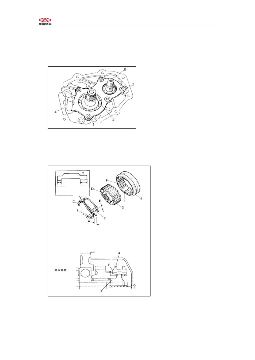
4、Install the bearing cover, insert the end of the bearing cover into the groove of 

the reserve、5th      guide shaft .Spread whorl glue on the bolt.   
Notice: Turn the output shaft, to check if it turns smoothly. 

  Whorl glue:262 glue   
Torque  :8~12 N·


1-Bolt 

2-Transmissan case 

3-Input shaft 

4-Reserve 、 5th  guide

shaft  

5-Output shaft

Fig.3-73 

5、Install the 5th hub sleeve、5th clutch hub、5th Synchronizer, insert and 5th snap 

ring. 
Notice: Keep the synchronizer insert short C、clutch hub D and hub    sleeve F inward
(5th gear side). 


1-5

th

 Spring snap spring 

2-5

th 

Synchronizer insert

3-5

th

 Clutch hub 

4-5

th

 Hub sleeve


Long 

Short 

A=B 

C: Short 

D: Long 

E:

 Insert 

F: Angle


Clutch side

Fig.3-74 


-88-  


Chery    QQ    Maintenance Manual                      Transmission System


5Shift guide  case assembly 
1、In case of disassembly or installing,  screw torque bolt,check-up blow hole 

straightway。 

Torque :  8~12N·m 
2、Clean  case  and  transmission  surface。 


1-Reserve、5

th

 Interlock bolt

2-Shift guide case 


A:Blow hole


Fig.3-81 

3、Install the select shaft assembly.   
Notice: When installing shift select shaft assembly, keep the shift    head in the 

middle position to prevent interlock bolt. 

4、Connect the shift    head and install the shift lever fork. 
5、  Screw down the shaft fork bolt. 
Torque  32~36N·m 


1-Shift head 

2-Shift select shaft   

3-Shift lever fork 

4-Fixup bolt


Fig.3-82 
 

6、Fix the shaft    restrict bolt.   
   Worm glue:262glue 

Torque  18~28N·m 


-89-  


Chery    QQ    Maintenance Manual                      Transmission System


1-Shift select shaft   

2-Interlock  

3-Shift lever fork 

4- Bolt 

5-Shaft restrict bolt


图 3-83 

7、Clean the contacting interface and spread sealed adhesive evenly. 
Sealed adhesive:seal glue(HZ1213Q/320222 YAP02-92) 
8、Install the transmission case assembly、clip and hanger assembly, 
Screw down the 4 bolt。   
Torque  8~12N·m 


1-Hang ring assembly 

2-Bolt 

3-Guide case assembly 

4-Special tool   

5-Clip  

6-Shift Shift fork shaft bolt 

7-Reserve、5

th

 Interlock bolt 

Fig.3-84 

9、Install the reserve backup light switch assembly reserve backup light switch 

Torque  18~28N·m 

10、Clean the interface of the transmission cover board and transmission, check 

the “O”Ring and screw down the three bolt. 

Torque  8~12N·m 


-90-  


Chery    QQ    Maintenance Manual                      Transmission System


1-Bolt 

2-Transmission cover

board


Fig.3-85 

6Clutch release shaft    system 

Fig.3-86 Clutch release shaft 

Round 


1-Spacer1 2-Release shaft assembly  3-Release spring  4-Spacer  5-Bolt  6-Nut 
7-Clip  8-Clutch  shaft 
Disassemble: 
1、Disassemble the clip ,loosen the   
bolt, remove the clutch   
2、Turn the release shaft, take   
out the release bearing.     
3、Use  plier  disassembly release  
shaft return spring。 

Fig.3-89 


-91-  


Content   ..  267  268  269  270   ..